Die for multi-angle side-punching machining

A side punching and multi-angle technology, applied in the field of stamping dies, can solve problems such as complex procedures, large number of dies, increased manufacturing costs and production cycles, and achieve the effects of reducing stamping costs, reducing the number of die sets, and shortening the production cycle

Inactive Publication Date: 2018-05-08
CHONGQING PINGWEI AUTOMOBILE TECH CO LTD
View PDF5 Cites 5 Cited by
  • Summary
  • Abstract
  • Description
  • Claims
  • Application Information

AI Technical Summary

Problems solved by technology

[0002] In the existing mold structure design, for side punching parts with different angles side by side, it is generally used to punch holes on different molds with different angles of wedges, that is, use a set of wedges in the first set of molds to punch out the first In the next set of molds, another set of wedges is used to punch out the second hole, which is simple in structure and easy to realize, but the number of molds is large and the process is complicated, which increases the manufacturing cost and production cycle.

Method used


Image

  • Die for multi-angle side-punching machining
  • Die for multi-angle side-punching machining
  • Die for multi-angle side-punching machining

Examples


Embodiment

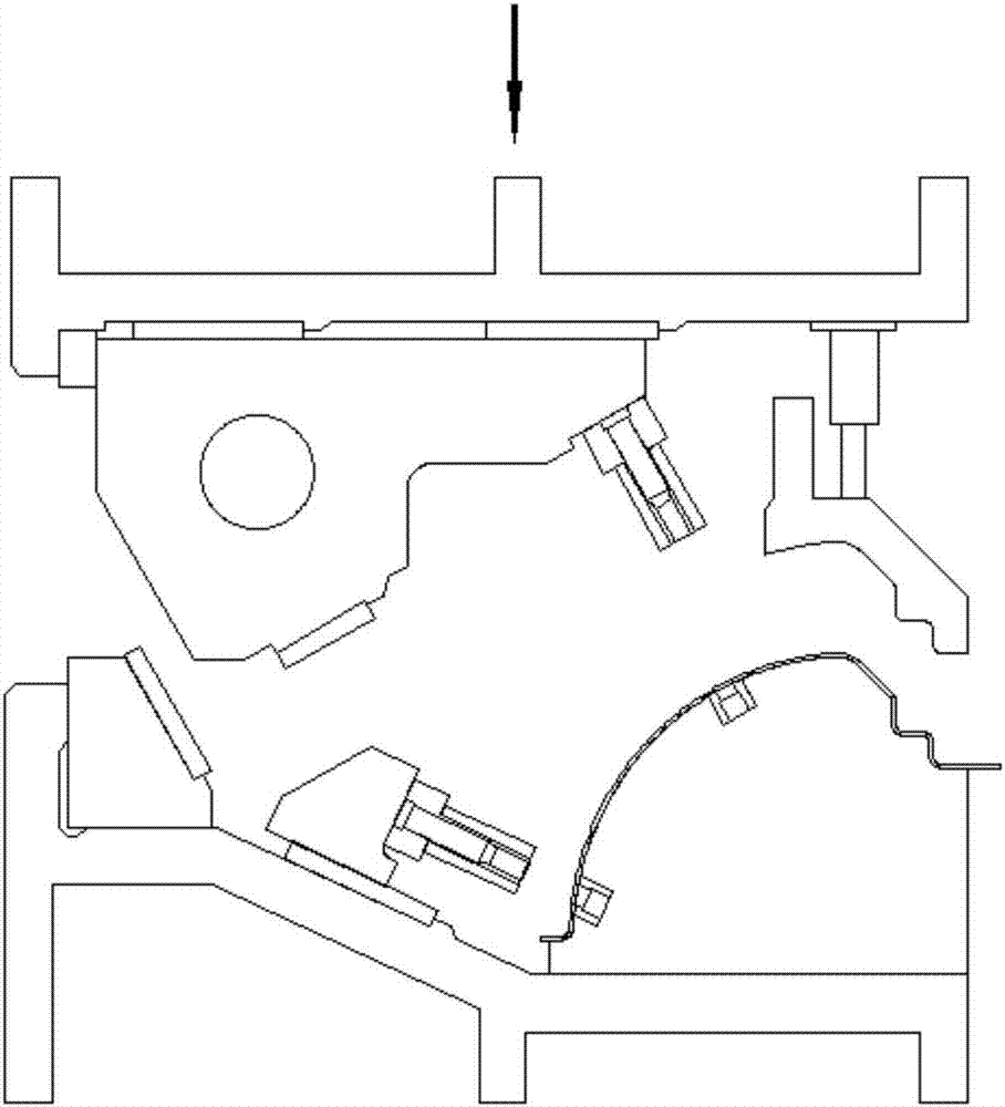
[0023] Such as figure 1 As shown, the part needs to be punched at two different positions, and the punching angles are different, that is, the first punching hole A and the second punching hole B; in the prior art, the first punching hole is punched out in the first set of molds Hole, punch out the second hole in the next set of molds, the processing cycle is longer, and the mold cost is higher.

[0024] Such as figure 2 As shown, the present invention provides a mold for multi-angle side punching, which is used to punch holes in different positions of the part 7, including an upper mold base 2, a lower mold base 1, a presser 6 and a lower punch 8. Among them, the presser 6 is set on the upper die base 2, and a nitrogen spring 4 is arranged between the upper die base 2, the lower punch 8 is set on the lower die base 1, and the lower punch 8 is provided with two Die 5 corresponding to each punching position.

[0025] The key is: the first wedge slider 14 is hoisted on the u...


PUM


Abstract

The invention provides a die for multi-angle side-punching machining. The die for multi-angle side-punching machining comprises an upper die base, a material pressing device arranged on the upper diebase, a lower die base and a lower male die arranged on the lower die base. A first tapered wedge sliding block is hoisted on the upper die base and provided with a first plunger chip and can transversely slide relative to the upper die base. The lower die base is provided with a second tapered wedge sliding block and a tapered wedge drive base which is used for driving the first tapered wedge sliding block to transversely move. The tapered wedge drive base and the side face of the first tapered wedge sliding block are provided with oblique fitting surfaces. The second tapered wedge sliding block is provided with a plunger chip. The second tapered wedge sliding block is arranged on the lower die base in a sliding manner, and the lower end of the first tapered wedge sliding block is provided with an oblique fitting surface. The lower male die is provided with a female die corresponding to the punching position of a part. According to the die for multi-angle side-punching machining, punching at different angles is completed through a set of tapered wedges in a procedure, the number of die sets is reduced, the punching cost is reduced, and the production period is shortened.

Description

technical field [0001] The invention belongs to the technical field of punching dies, and relates to a die for multi-angle side punching processing. Background technique [0002] In the existing mold structure design, for side punching parts with different angles side by side, it is generally used to punch holes on different molds with different angles of wedges, that is, use a set of wedges in the first set of molds to punch out the first In the next set of molds, another set of wedges is used to punch out the second hole. This structure is simple and easy to realize, but the number of molds is large and the process is complicated, which increases the manufacturing cost and production cycle. Contents of the invention [0003] In view of the deficiencies of the prior art described above, the purpose of the present invention is to provide a mold for multi-angle side punching, which can realize punching at different angles on the same set of molds and reduce the cost of mold...

Claims


Application Information

Patent Timeline
Patent Type & Authority Applications(China)
IPC IPC(8): B21D28/34
CPCB21D28/34
Inventor 刘庆辉杨晓东王卫生姚小强
Owner CHONGQING PINGWEI AUTOMOBILE TECH CO LTD
Why Eureka
Try Eureka