Space-division multiplexing optical network crosstalk monitoring, source tracing and optical path re-optimization method

A technology of multiplexing light and re-optimization, applied in the field of optical network communication, it can solve problems such as inability to obtain crosstalk service data related information, routing and resource allocation restrictions, and inability to recover signals, so as to ensure service transmission quality, improve reliability and improve reliability. real-time effects

Active Publication Date: 2018-05-04
TSINGHUA UNIV
View PDF5 Cites 12 Cited by
  • Summary
  • Abstract
  • Description
  • Claims
  • Application Information

AI Technical Summary

Problems solved by technology

However, the introduction of these new optical fibers has brought restrictions on routing and resource allocation to optical networks. Among them, the most important limitation is the limitation of cumulative crosstalk, that is, two optical signals of the same wavelength are in adjacent fiber cores or different The transmission between modes will generate crosstalk, and the crosstalk will accumulate along the transmission path. Once the accumulated crosstalk exceeds a certain value, the receiver will not be able to restore the original signal
[0003] However, due to the power aliasing of the crosstalk signal and the service signal, it is usually impossible to obtain the crosstalk service data and related information, and it is difficult to further block it or re-optimize the route in a targeted manner to avoid or reduce its interference on the service signal

Method used


Image

  • Space-division multiplexing optical network crosstalk monitoring, source tracing and optical path re-optimization method
  • Space-division multiplexing optical network crosstalk monitoring, source tracing and optical path re-optimization method
  • Space-division multiplexing optical network crosstalk monitoring, source tracing and optical path re-optimization method

Examples


Embodiment Construction

[0030] The embodiments of the present invention are described in detail below. Examples of the embodiments are shown in the accompanying drawings, in which the same or similar reference numerals indicate the same or similar elements or elements with the same or similar functions. The embodiments described below with reference to the accompanying drawings are exemplary, and are intended to explain the present invention, but should not be construed as limiting the present invention.

[0031] The following describes the crosstalk monitoring, source tracing and optical path reoptimization methods proposed in the space division multiplexing optical network according to the embodiments of the present invention with reference to the accompanying drawings.

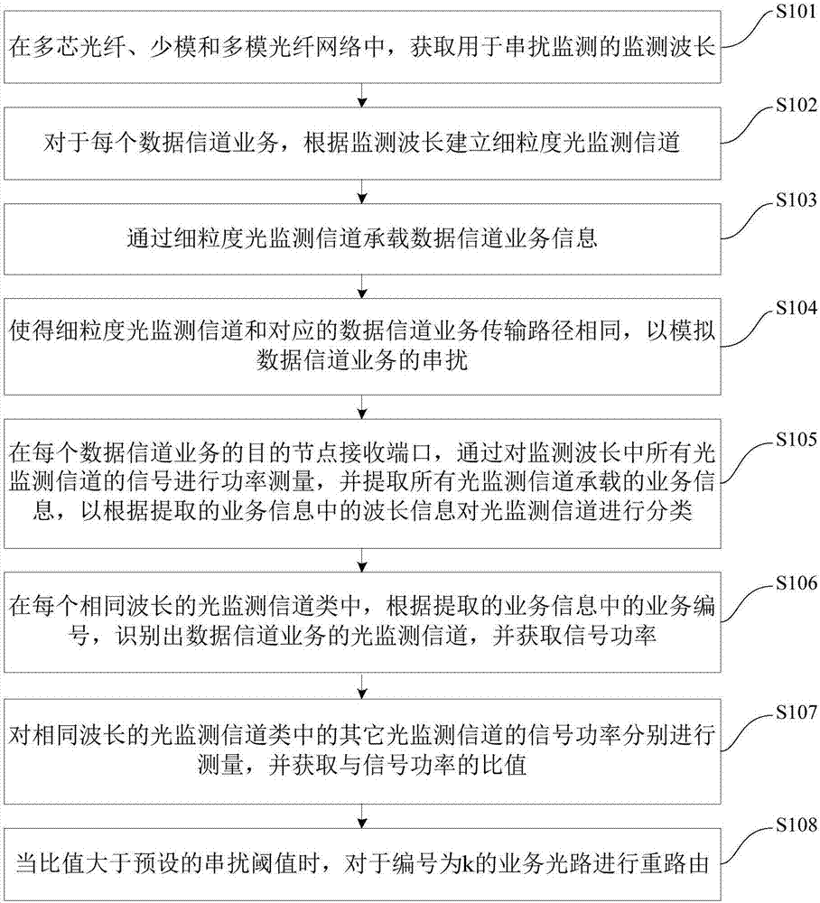
[0032] figure 1 It is a flowchart of a method for crosstalk monitoring, traceability, and optical path reoptimization in a space division multiplexing optical network according to an embodiment of the present invention.

[0033] Such as...


PUM


Abstract

The invention discloses a space-division multiplexing optical network crosstalk monitoring, source tracing and optical path re-optimization method, comprising the following steps: acquiring a monitoring wavelength for crosstalk monitoring; building a fine grit optical monitoring channel; bearing a data channel service information; simulating crosstalk of the data channel service; classifying the optical monitoring channels according to a wavelength information in the extracted service information; identifying the optical monitoring channel of the data channel service, and acquiring a signal power P<0>; respectively measuring the signal power P<k> of the other optical monitoring channels in the type of the optical monitoring channels of same wavelength, and acquiring a ratio XT<k> to the signal power P<0>; and when the ratio XT<k> is greater than a preset crosstalk threshold value XT, performing rerouting for a service optical path of which a serial number is k. The method providedby the invention can perform power measurement and information extraction for the signals of all the optical monitoring channels in the monitoring wavelength to realize crosstalk monitoring and sourcetracing, can perform rerouting for the optical path with serious crosstalk, thereby, effectively improves reliability and real-time performance of crosstalk monitoring and optical path re-optimization.

Description

Technical field [0001] The present invention relates to the technical field of optical network communication, in particular to a method for monitoring, traceability and optical path re-optimization of a space division multiplexing optical network crosstalk. Background technique [0002] With the rapid growth of optical network bandwidth requirements, space division multiplexing technology based on multi-core fiber, few-mode fiber and multi-mode fiber is widely used in backbone optical networks to further expand transmission capacity while reducing network costs. However, the introduction of these new optical fibers has brought restrictions on routing and resource allocation to optical networks. Among them, the most important limitation is the limitation of cumulative crosstalk, that is, two optical signals of the same wavelength are in adjacent cores or different Transmission between modes will produce crosstalk, and the crosstalk will accumulate along the transmission path. Once...

Claims


Application Information

Patent Timeline
IPC IPC(8): H04B10/079H04Q11/00
CPCH04B10/07955H04Q11/0005H04Q11/0062H04Q2011/0024H04Q2011/0083H04Q2011/0084
Inventor 郑小平罗瑞杰华楠
Owner TSINGHUA UNIV
Why Eureka
Try Eureka