
Underwater umbilical cable terminal dragging system

An umbilical cable terminal and watertight technology, applied in the direction of electrical components, base/housing, coupling devices, etc., can solve the problems of limited drag carrying capacity, weakened reliability, simple structure, etc., and achieve improved equipment reliability, high technical level, Easy to install

Pending Publication Date: 2018-05-04
上海禹海科技有限公司
View PDF0 Cites 5 Cited by
  • Summary
  • Abstract
  • Description
  • Claims
  • Application Information

AI Technical Summary

Problems solved by technology

[0004] The existing umbilical cable terminal equipment generally adopts packing sealing technology, and the structure is simple. The basic operation principle is to fill the middle of the cable and the compression ring with a soft material, and tighten the compression ring to increase the compactness between the soft material and the cable sheath. To achieve sealing, but this technology is only applicable to relatively shallow water depth requirements, and the application water depth is within 1000m, but for environments with water depths higher than 1000m, the reliability of this sealing form will be greatly weakened or even invalid
In addition, the dragging function of the packing seal is realized by the friction between the external compression ring device and the umbilical cable sheath, and the dragging capacity is limited. At the same time, the technical structure is simple, and it is difficult to realize complex construction and high water depth pressure environment equipment application
[0005] At present, umbilical cable end vulcanization technology is also used for sealing. This technology can meet the requirements of relatively deep underwater construction. However, under the working conditions of equipment construction and towing, due to the flexible tension of the external umbilical cable itself, it will accelerate the destruction of its watertight reliability. , resulting in failure

Method used


Image

  • Underwater umbilical cable terminal dragging system
  • Underwater umbilical cable terminal dragging system
  • Underwater umbilical cable terminal dragging system

Examples


Embodiment

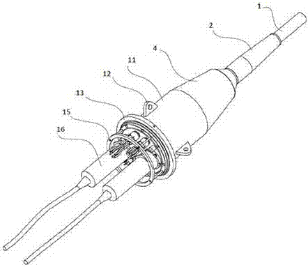
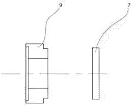
[0033] Examples, such as Figure 1-3 As shown, an underwater umbilical cable terminal towing system includes a sealed shell 4, and the sealed shell 4 has a truncated cone shape.

[0034] The sealing shell 4 has a big head end and a small head end. The small head end of the sealing shell 4 is threadedly connected with a compression nut 3, and the compression nut 3 is connected with the sealing shell 4 to compress the outer sheath of the cable.

[0035] A cylindrical pressure cabin 11 is fixedly connected to the big end of the sealed shell 4.

[0036] The sealed shell 4 has a first cavity 20 and a second cavity 21. The first cavity 20 and the second cavity 21 are in communication with each other. The first cavity 20 and the second cavity 21 are both cylindrical cavities. A cavity 20 and the second cavity 21 are arranged coaxially, a step 22 is formed between the first cavity 20 and the second cavity 21, and the first cavity 20 is arranged at a position close to the small end of the se...


PUM


Abstract

The invention discloses an underwater umbilical cable terminal dragging system, which comprises a seal housing. A first cavity and a second cavity are arranged in the seal housing; a taper sleeve is arranged in the first cavity; a base plate is arranged in the second cavity; a limiting ring is arranged between the base plate and the taper sleeve. The underwater umbilical cable terminal dragging system provided by the invention can meet the working requirements on electric power supply, signal transmission, high pressure liquid gas pipeline distribution, control and dragging, and the like of afull sea deep water device, so that the reliability is greatly improved; a dragging and supporting mechanism can reach up to 95 percent or more of a self-bearing capacity of an umbilical cable, so that a higher technical level is reached.

Description

Technical field [0001] The invention relates to an underwater umbilical cable terminal towing system, which is widely used in marine construction [0002] Field of operation. Background technique [0003] The underwater umbilical cable terminal towing system is an important component of the underwater control, underwater production system, and underwater monitoring system. The umbilical terminal towing system is the central distribution system of the underwater control, production system and monitoring system, and its role is to achieve Power supply, signal transmission, distribution, control and towing of high-pressure liquid and gas pipelines for underwater equipment. [0004] Existing umbilical cable terminal equipment generally adopts packing sealing technology with simple structure. The basic operating principle is to fill the soft material between the cable and the compression ring, and tighten the compression ring to increase the density between the soft material and the cabl...

Claims


Application Information

Patent Timeline
Patent Type & Authority Applications(China)
IPC IPC(8): H01R13/52H02G3/06
CPCH01R13/5205H02G3/0625
Inventor 张军
Owner 上海禹海科技有限公司
Learn More