
Directional dual-frequency antenna

A dual-band antenna, low-frequency technology, applied in the direction of antenna, antenna coupling, antenna components, etc., can solve the problems of unfavorable development of miniaturization of mobile terminals, large size of antenna system, large size of electronic equipment, etc., to avoid cumbersome assembly and high cost. Gain, simple structure effect

Pending Publication Date: 2018-05-04
江苏吴通物联科技有限公司
View PDF8 Cites 0 Cited by
  • Summary
  • Abstract
  • Description
  • Claims
  • Application Information

AI Technical Summary

Problems solved by technology

However, this will lead to a large volume of the antenna system, which is not conducive to the miniaturization of mobile terminals, especially in devices with small volume, such as mobile phones and other equipment, if the antenna volume is too large, the volume of electronic equipment will be very large. Big

Method used


Image

  • Directional dual-frequency antenna

Examples


Embodiment 1

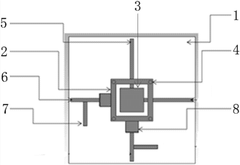
[0020] Example 1: see figure 1 As shown, a directional dual-frequency antenna includes a low-frequency radiation unit 2, a high-frequency radiation unit 3, and a PCB board 1, from high to low. The low-frequency radiation unit 2, the high-frequency radiation unit 3 are fixed on the fixed stud 4 Right above the PCB board 1, the low-frequency radiation unit 2 is provided with an opening, and the PCB board 1 is also provided with a high-frequency feeder 5, a low-frequency feeder 6, a 1 / 4-wavelength isolation short-circuit line 7 and a coupling feeder Sheet 8, the low-frequency radiating unit 2 and the high-frequency radiating unit 3 are in the same space, and the stacked arrangement can effectively reduce the size of the antenna while simultaneously achieving dual-frequency coverage.

[0021] See figure 1 As shown, the low-frequency feed line 6 is connected to the isolated short-circuit line 7 or the high-frequency feed line 5 is connected to the isolated short-circuit line 7, or th...


PUM


Abstract

The invention discloses a directional dual-frequency antenna which is characterized by sequentially comprising a low-frequency radiating unit, a high-frequency radiating unit and a PCB from high to low. The low-frequency radiating unit and the high-frequency radiating unit are fixed over the PCB through fixing studs. The low-frequency radiating unit is provided with an opening, and the PCB is alsoprovided with a high-frequency feed line, a low-frequency feed line, a 1 / 4 wavelength isolation short-circuit line and a coupling feed slice. By stacking the low-frequency radiating unit and the high-frequency radiating unit, the size of the antenna is effectively reduced, dual-frequency coverage is achieved, the isolation short-circuit line is increased, and the isolation between high and low frequencies is improved.

Description

Technical field [0001] The invention relates to the field of wireless communication, in particular to a directional dual-frequency antenna. Background technique [0002] The communication system is a combination of wired and wireless. The transmission and reception of space wireless signals are realized by antennas. It can be seen that the antenna plays a vital role in the wireless communication system. MIMO (Multiple-Input Multiple-Output) technology refers to the use of multiple transmitting antennas and receiving antennas at the transmitting end and the receiving end respectively, so that signals are transmitted and received through multiple antennas at the transmitting and receiving ends, thereby improving communication quality. It can make full use of space resources and achieve multiple transmissions and multiple receipts through multiple antennas. Without increasing spectrum resources and antenna transmission power, it can double the system channel capacity, showing obviou...

Claims


Application Information

Patent Timeline
Patent Type & Authority Applications(China)
IPC IPC(8): H01Q1/36H01Q1/38H01Q1/50H01Q1/52H01Q5/20
CPCH01Q1/36H01Q1/38H01Q1/50H01Q1/521H01Q5/20
Inventor 鲍晋朝黄克猛陈晓飞
Owner 江苏吴通物联科技有限公司
Learn More