Jet Nozzles for Gentle Combustion Chambers of Gas Turbines
A technology of jet nozzles and gas turbines, which is applied in combustion chambers, continuous combustion chambers, combustion methods, etc., can solve the problems of unfavorable establishment and realization of soft combustion, reduction of flue gas return ratio, and large pressure loss, and achieve ultra-low nitrogen oxidation The effect of reducing the emission of pollutants, reducing the peak flame temperature, and reducing the pressure loss
Active Publication Date: 2019-10-01
INST OF ENGINEERING THERMOPHYSICS - CHINESE ACAD OF SCI
View PDF5 Cites 0 Cited by
- Summary
- Abstract
- Description
- Claims
- Application Information
AI Technical Summary
Problems solved by technology
In general, in order to ensure uniform mixing of fuel and air, the nozzle adopts a strong swirl design. On the one hand, such a design often causes a large pressure loss, and the reaction zone is close to the outlet of the nozzle, which may easily cause local overheating of the nozzle. On the other hand, , the strong swirling jet of the nozzle will weaken the recirculation zone and reduce the flue gas recirculation ratio, which is not conducive to the establishment and realization of soft combustion
Method used
View moreImage
Smart ImageViewing Examples
Examples
Embodiment Construction
Login to View More PUM
 Abstract
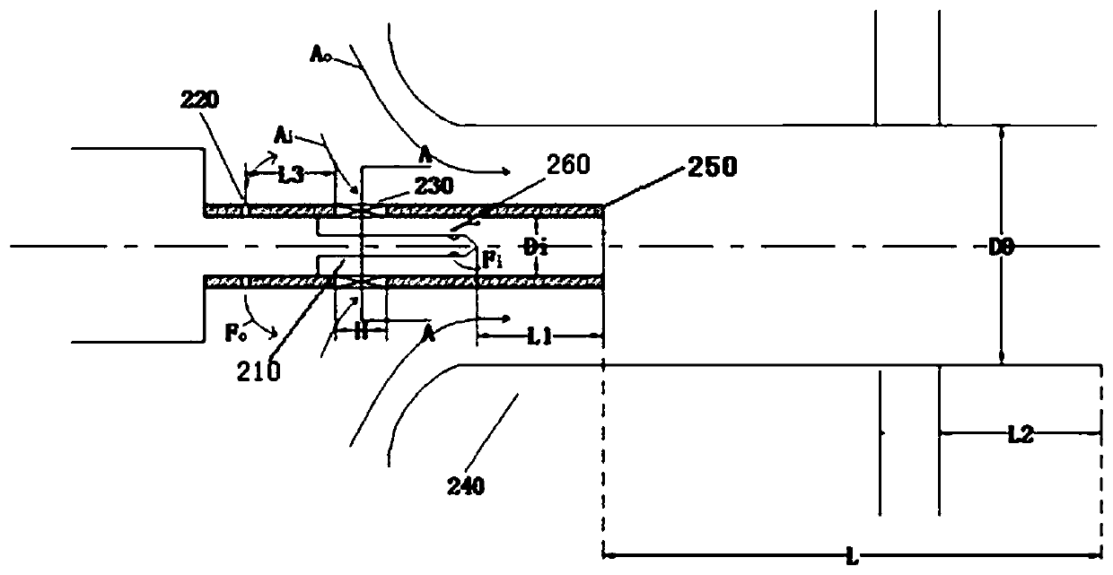
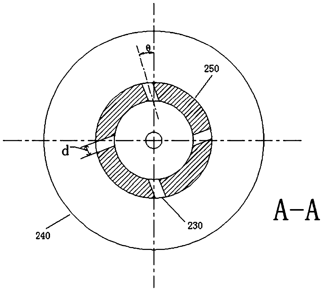
A jet nozzle of a mild combustion chamber of a gas turbine comprises a fuel inside nozzle, a fuel outside spray hole, multiple rotational flow groove channels, an outside pipeline and an inside pipeline. The mixing uniformity of fuel and air at a jet nozzle outlet is improved, the outside fuel-air equivalence ratio is relatively low, flame root lifting is facilitated, too-early ignition does not occur easily, jets of the jet nozzle belong to weak rotational flows, the overall pressure loss is relatively low, the axial speed is not prone to attenuation, and increase of the smoke reflux ratio ofthe combustion chamber is facilitated.
Description
technical field The invention relates to the technical field of gas turbines, in particular to a jet nozzle for a soft combustion chamber of a gas turbine. Background technique Nitrogen oxides include nitrous oxide, nitrogen monoxide, and nitrogen dioxide. Nitrogen oxides, as the main air pollutants, can cause poisonous damage to animals and plants, and are also one of the main causes of acid rain, acid fog and photochemical smog. Gas turbine is an important power equipment. On the one hand, it is necessary to continuously increase the outlet temperature of the combustion chamber to improve the efficiency of the gas turbine. On the other hand, it is necessary to further reduce the emission of nitrogen oxides in a wide range of operating conditions. Under the premise of maintaining combustion efficiency and performance, reducing the emission of nitrogen oxides has always been the key goal of gas turbine combustion researchers. For gas turbines whose combustor outlet temper...
Claims
Login to View More Application Information
Patent Timeline
 Patent Type & Authority Patents(China)
IPC IPC(8): F23R3/28F23R3/38
Inventor 熊燕刘耘州俞镔张哲巅肖云汉
Owner INST OF ENGINEERING THERMOPHYSICS - CHINESE ACAD OF SCI
Features
- Generate Ideas
- Intellectual Property
- Life Sciences
- Materials
- Tech Scout
- Unparalleled Data Quality
- Higher Quality Content
- 60% Fewer Hallucinations
Learn More Browse by: Latest US Patents, China's latest patents, Technical Efficacy Thesaurus, Application Domain, Technology Topic, Popular Technical Reports.
© 2025 PatSnap. All rights reserved.Legal|Privacy policy|Modern Slavery Act Transparency Statement|Sitemap|About US| Contact US: help@patsnap.com


