
Smart card storing, taking and carrying device

A technology of handling device and smart card, which is applied in the directions of transportation and packaging, stacking receiving device, separation of objects, etc., can solve the problems of delaying the use of cards for production equipment, restricting production and processing efficiency, restricting handling efficiency, etc. Good effect and high handling efficiency

Pending Publication Date: 2018-05-04
GUANGZHOU MINGSEN TECH CO LTD
View PDF9 Cites 3 Cited by
  • Summary
  • Abstract
  • Description
  • Claims
  • Application Information

AI Technical Summary

Problems solved by technology

[0005] 1. When using the suction cup to work, only one card can be transported at a time, so the transport efficiency is low
[0006] 2. It takes a long time for the suction cup to complete a card handling work. In this way, when the next card arrives, because the previous card has not completed the handling task, the next card can only stop waiting, thus restricting the handling efficiency. At the same time, due to the long handling period, it will delay the use of cards for the next production equipment, thus restricting the production and processing efficiency

Method used


Image

  • Smart card storing, taking and carrying device
  • Smart card storing, taking and carrying device
  • Smart card storing, taking and carrying device

Examples


Embodiment 1

[0049] The vertical drive mechanism is connected with the slide block in the screw drive mechanism, and the rotation drive mechanism and the telescopic drive mechanism are sequentially connected below the vertical drive mechanism.

Embodiment 2

[0051] The rotary drive mechanism is connected with the slide block in the screw drive mechanism, and the vertical drive mechanism and the telescopic drive mechanism are sequentially connected under the rotary drive mechanism.

[0052] In the above-mentioned embodiment 1 and embodiment 2, although the installation positions of the rotary drive mechanism and the vertical drive mechanism are different, it does not affect the realization of the functions of each mechanism.

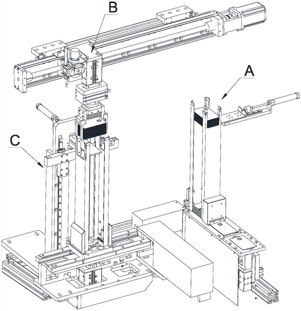
[0053] When working, the rotation of the screw rod drives the slider to rotate, and then drives the guide rod cylinder connected to the slider, the rotary cylinder, the slide cylinder, the claw C1 and the card set to go back and forth between the card taking mechanism A and the card storage mechanism B. horizontal movement. The advantage of this setting is that the screw drive mechanism has high motion precision and stable operation, and can accurately stay above the card bucket D1 in the card taking mechanis...


PUM


Abstract

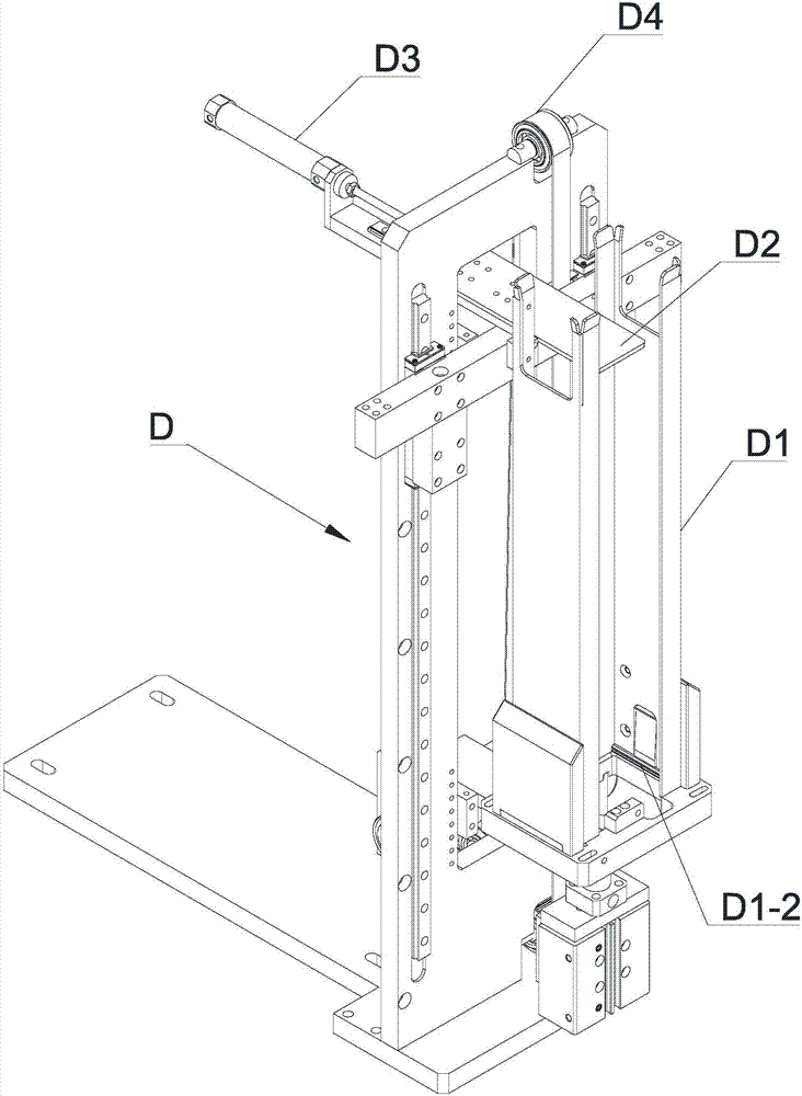
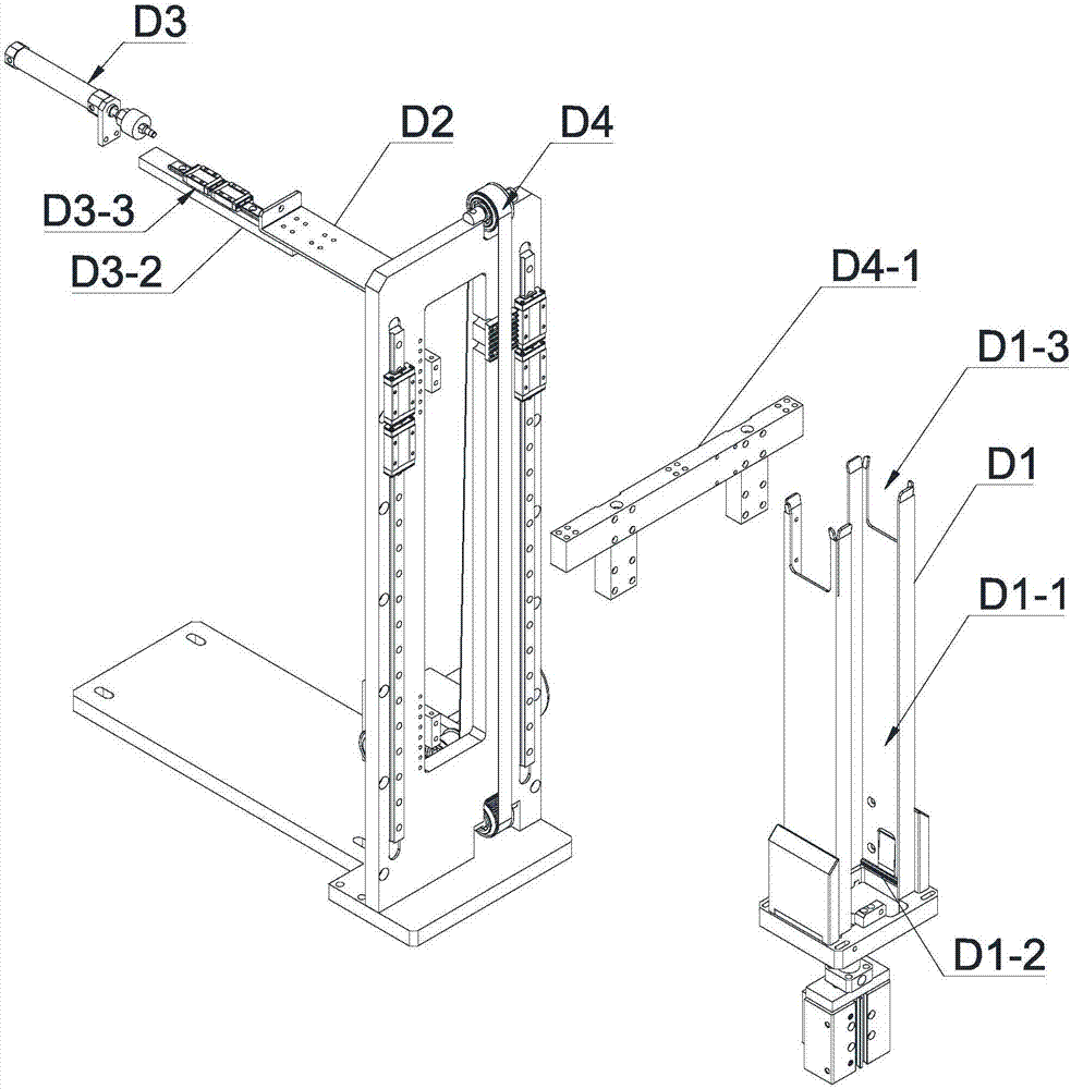
The invention discloses a smart card storing, taking and carrying device which comprises a card taking mechanism, a card storing mechanism and a transition carrying mechanism. Vertical carrying mechanisms are arranged on the card taking mechanism and the card storing mechanism correspondingly, and each vertical carrying mechanism comprises a card hopper, a supporting plate, an in-out driving mechanism for driving the supporting plate to get into and out of the card hopper in the side direction, and a lifting driving mechanism for driving the supporting plate to make vertical card storing movement. The transition carrying mechanism comprises two clamping jaws, a telescopic driving mechanism for driving the two clamping jaws to relatively move to achieve card clamping and storing, a horizontal carrying mechanism for driving the two clamping jaws to horizontally move, and a vertical driving mechanism for driving the two clamping jaws to make lifting movement. Each clamping jaw comprises alateral positioning part and a card supporting part arranged below the lateral positioning part, and the card supporting parts of the two clamping jaws extend to each other. According to the smart card storing, taking and carrying device, a plurality of cards can be carried and stored into the card hoppers at a time, and the smart card storing, taking and carrying device has the advantages that carrying is stable, the carrying efficiency is high, and storing is tidy.

Description

technical field [0001] The invention relates to a smart card production equipment, in particular to a smart card access and transport device. Background technique Background technology 1: [0002] During the production process of smart cards, the cards need to be transferred to the card hopper for storage. When storing, the cards enter the card hopper from the upper end of the card hopper, and then move downward and stack on the baffle at the bottom of the card hopper. In this way, when the card issuing task is performed, the card issuing device (such as a suction cup power device) at the bottom of the card bucket transports the card from the baffle plate located in the card bucket to the card conveying track, and then the card conveying mechanism (such as a synchronous belt dial) tooth mechanism) to each station for processing. [0003] Among them, when the card is stored in the card bucket, since the card bucket has a certain depth in the vertical direction, when the ca...

Claims


Application Information

Patent Timeline
Patent Type & Authority Applications(China)
IPC IPC(8): B65H83/00B65H31/10B65H1/14B65H29/00
CPCB65H1/14B65H29/003B65H31/10B65H83/00B65H2701/1914B65H2405/111
Inventor 郝宁钟永雄徐飞
Owner GUANGZHOU MINGSEN TECH CO LTD
Learn More