Electric bicycle charging pile
A technology of electric bicycles and charging piles, which is applied to electric vehicle charging technology, bicycles, electric vehicles, etc., to achieve the effect of solving random parking, high safety factor, and solving the inconvenience of returning the car
- Summary
- Abstract
- Description
- Claims
- Application Information
AI Technical Summary
Problems solved by technology
Method used
Image
Examples
Embodiment 1
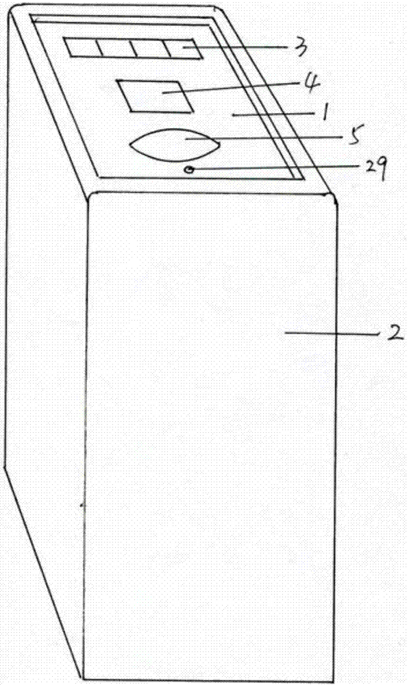
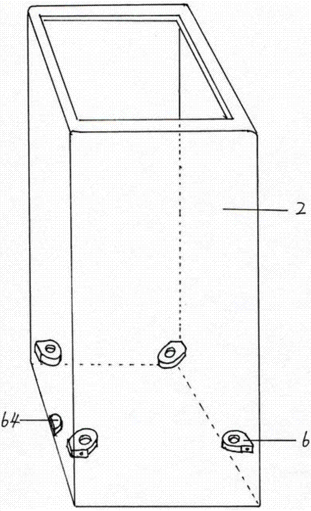
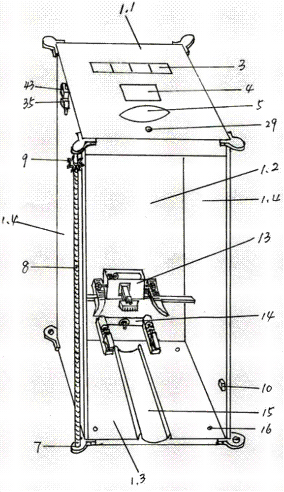
[0038] A kind of electric bicycle charging pile (referring to image 3 and Figure 4 ), including a charging pile body consisting of a top plate 1.1, a bottom plate 1.3, a rear plate 1.2 and two side plates 1.4, a touch sensor screen 5 and a power display screen 3 are installed above the top plate 1.1, and a charging pile is located below the top plate 1.1. A program processor 11 and a car number recognition instrument 12 are installed in the pile body, and a wheel guide groove 15 is arranged in the charging pile body on the bottom plate 1.3; the wheel shaft buckle lock system 14 is installed on the back plate 1.2 above the wheel guide groove 15; An integrated plug system 13 is installed in the charging pile body above the system 14; an infrared sensor 10 is installed in the lower part of the charging pile body. The base plate is also provided with shape body fixing holes 16, and there are at least four shape body fixing holes 16, which are arranged at the four corners of the...
Embodiment 2
[0040] A kind of electric bicycle charging pile (referring to image 3 and Figure 4), including a charging pile body consisting of a top plate 1.1, a bottom plate 1.3, a rear plate 1.2 and two side plates 1.4, a touch sensor screen 5 and a power display screen 3 are installed above the top plate 1.1, and a charging pile is located below the top plate 1.1. A program processor 11 and a car number recognition instrument 12 are installed in the pile body, and a wheel guide groove 15 is arranged in the charging pile body on the bottom plate 1.3; the wheel shaft buckle lock system 14 is installed on the back plate 1.2 above the wheel guide groove 15; An integrated plug system 13 is installed in the charging pile body above the system 14; an infrared sensor 10 is installed in the lower part of the charging pile body.
[0041] The integrated plug system described ( Figure 3-Figure 6 ) includes a U-shaped integrated plug system fixture made up of the outrigger 27 and the outrigger ...
Embodiment 3
[0044] On the basis of Embodiment 2, this embodiment makes further improvements to the technical solution of Embodiment 2 for the convenience of use and consideration of installation, and the specific improvements are as follows:
[0045] Further, four screw rods 8 are installed on the outside of the charging pile body 1 (see image 3 ), each threaded rod 8 is installed on the charging pile body 1 through a set of threaded rod holders 7 at both ends, and each threaded rod 8 is equipped with a cone 9, and the four cones 9 are on the same plane. An elevating motor 62 is installed on the outside of body 1, and elevating gear 63 is installed on the output end of elevating motor 62, and elevating gear 63 is connected in series with four cones 9 by chain 21 (referring to Figure 9 ).
[0046] A bearing 17 (see Figure 8 ).
[0047] The screw mandrel 8 is installed on the four vertical edges of the charging pile body 1 (see image 3 ).
[0048] Described cone 9 is installed on t...
PUM
 Abstract
Description
Claims
Application Information
 - R&D
- Intellectual Property
- Life Sciences
- Materials
- Tech Scout
- Unparalleled Data Quality
- Higher Quality Content
- 60% Fewer Hallucinations
Browse by: Latest US Patents, China's latest patents, Technical Efficacy Thesaurus, Application Domain, Technology Topic, Popular Technical Reports.
© 2025 PatSnap. All rights reserved.Legal|Privacy policy|Modern Slavery Act Transparency Statement|Sitemap|About US| Contact US: help@patsnap.com


