
New-energy car speed reducer parking gear manufacturing technology

A technology for new energy vehicles and parking gears, applied in the field of forging and forming, can solve the problems of waste of raw materials, low production efficiency of cutting processing and high cost, and achieve the effects of reasonable technical route, saving raw materials and high production efficiency

Inactive Publication Date: 2018-05-04
江苏威鹰机械有限公司
View PDF7 Cites 8 Cited by
  • Summary
  • Abstract
  • Description
  • Claims
  • Application Information

AI Technical Summary

Problems solved by technology

The disadvantage is that the cutting production efficiency is low, and it is only suitable for single-piece or small-batch production applications. Secondly, the cutting process is used to form the tooth surface, which wastes raw materials, high cost, and the metal flow line is cut off. The phenomenon of being damaged and unable to shift gears

Method used


Image

  • New-energy car speed reducer parking gear manufacturing technology
  • New-energy car speed reducer parking gear manufacturing technology
  • New-energy car speed reducer parking gear manufacturing technology

Examples


Embodiment

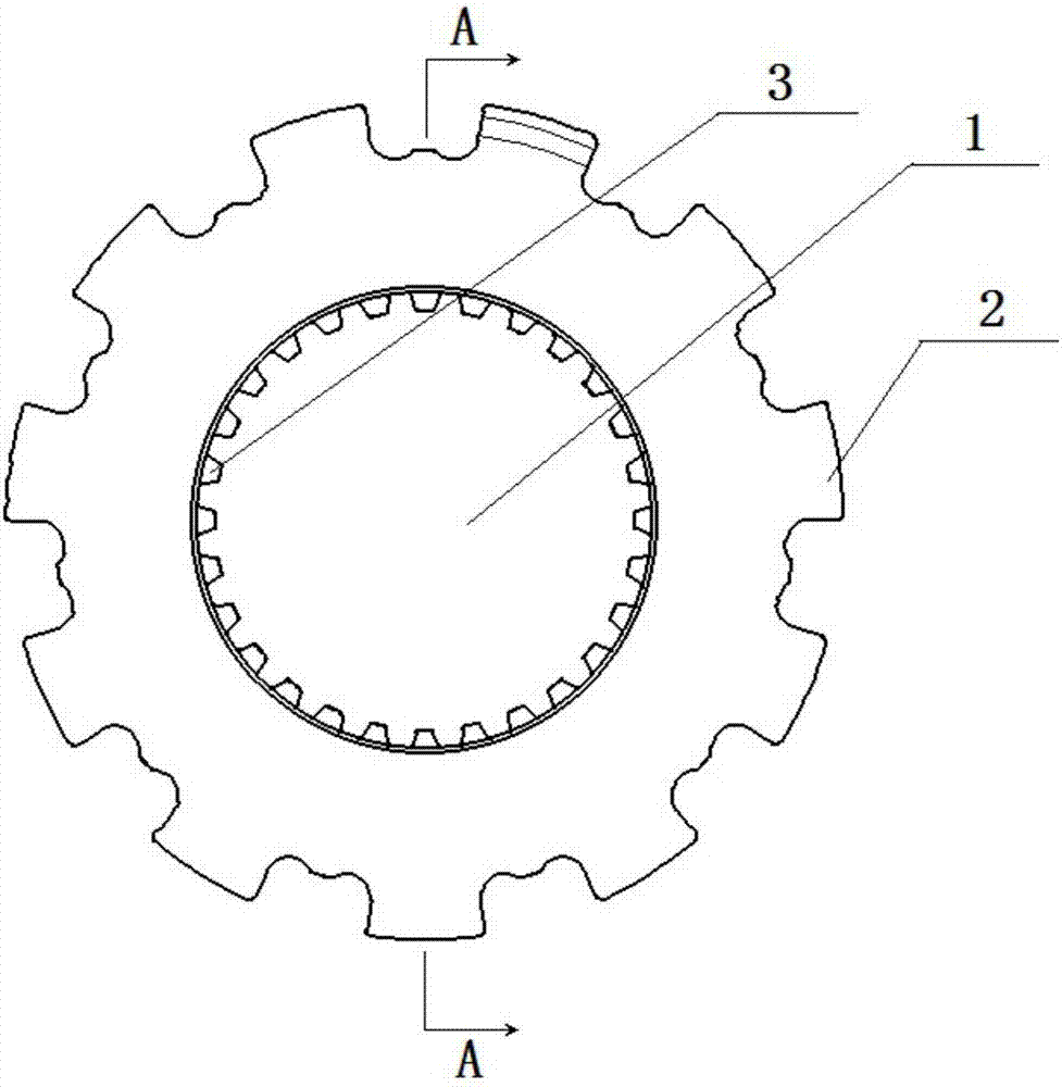
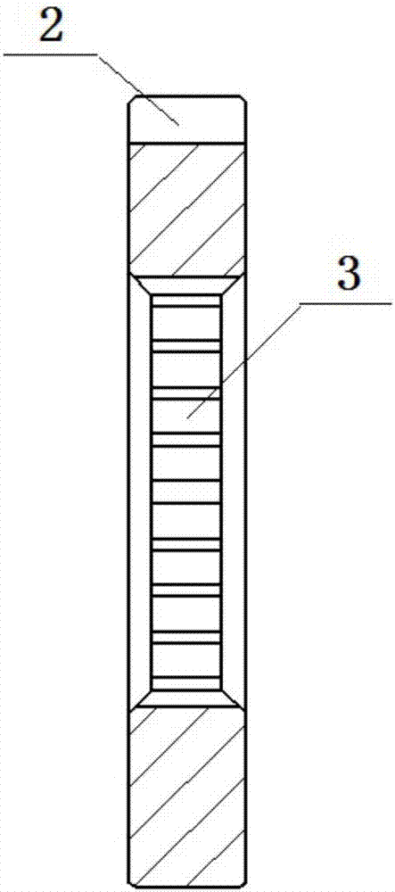
[0014] Example: see figure 1 with figure 2 As shown, a new energy vehicle reducer parking gear includes a circular plate body with a thickness of 8-12 mm. The circular plate body is provided with a central hole 1 and an outer tooth surface 2 is provided on the outer side of the circular plate body. , The addendum circle of the outer tooth surface 2 is 100 mm, and the root circle is 80mm; the inner tooth surface 3 is provided with the addendum circle of the inner tooth surface 3 is 40mm, and the tooth root circle is 30mm; the circular plate body is an integral structure Forged from metal.

[0015] See image 3 As shown, the manufacturing process includes the following steps: ① blanking: select the metal bar of the corresponding diameter according to the requirements of the product design drawing, and cut the required length; ② spheroidizing annealing: send the billet into the annealing furnace and heat it to 720 ℃-780 ℃ for spheroidizing annealing treatment, spheroidizing rate ≥...


PUM

PropertyMeasurementUnit
Surface hardnessaaaaaaaaaa

Abstract

The invention discloses a new-energy car speed reducer parking gear manufacturing technology. According to the technology, at first, cold extruding is carried out to remove the bottom so that a hollowcylindrical shaft can be formed, then the outer tooth face and the inner tooth face of the hollow cylindrical shaft are formed in a cold forging and extruding manner, and finally cutting is carried out, so that a plurality of new-energy car speed reducer parking gears are formed. The manufacturing technology is reasonable in technical route, metal flow is not cut off, the strength of product tooth faces is high, raw materials are saved, and the production efficiency is high.

Description

Technical field [0001] The invention belongs to the technical field of forging forming, and specifically relates to a manufacturing process for a parking gear of a reducer. Background technique [0002] The parking gear of the automobile reducer includes a circular plate body. The circular plate body is provided with a central hole 1, an outer tooth surface 2 and an inner tooth surface 3 on the inner side. The existing manufacturing process: directly select a rod Material cutting, hobbing to form the external tooth surface, and then using the method of gear shaping to form the internal tooth surface. The disadvantage is that the cutting production efficiency is low, only suitable for single-piece or small batch production applications, followed by the application of cutting processing technology to shape the tooth surface, waste of raw materials, high cost, metal streamlines are cut, the tooth surface strength is low, and teeth are prone to appear The phenomenon of being damaged...

Claims


Application Information

Patent Timeline
IPC IPC(8): B23P15/14
CPCB23P15/14
Inventor 张太良万永福申剑
Owner 江苏威鹰机械有限公司
Learn More