
ct system and its detection device

A detection device and accommodating cavity technology, applied in medical science, diagnosis, computerized tomography scanner, etc., to achieve the effect of improving image quality, reducing temperature, and ensuring image imaging effect

Active Publication Date: 2021-08-17
SHANGHAI UNITED IMAGING HEALTHCARE
View PDF10 Cites 0 Cited by
  • Summary
  • Abstract
  • Description
  • Claims
  • Application Information

AI Technical Summary

Problems solved by technology

[0003] Based on this, it is necessary to provide a detection device that can avoid the temperature coupling of the heat source and avoid the influence of the temperature on the response stability in view of the problem that the superposition of heat generated by the current reference detector affects the response of the reference detector. CT system of detection device

Method used


Image

  • ct system and its detection device
  • ct system and its detection device
  • ct system and its detection device

Examples


Embodiment Construction

[0042] In order to make the purpose, technical solution and advantages of the present invention clearer, the CT system and its detection device of the present invention will be further described in detail below through embodiments and in conjunction with the accompanying drawings. It should be understood that the specific embodiments described here are only used to explain the present invention, not to limit the present invention.

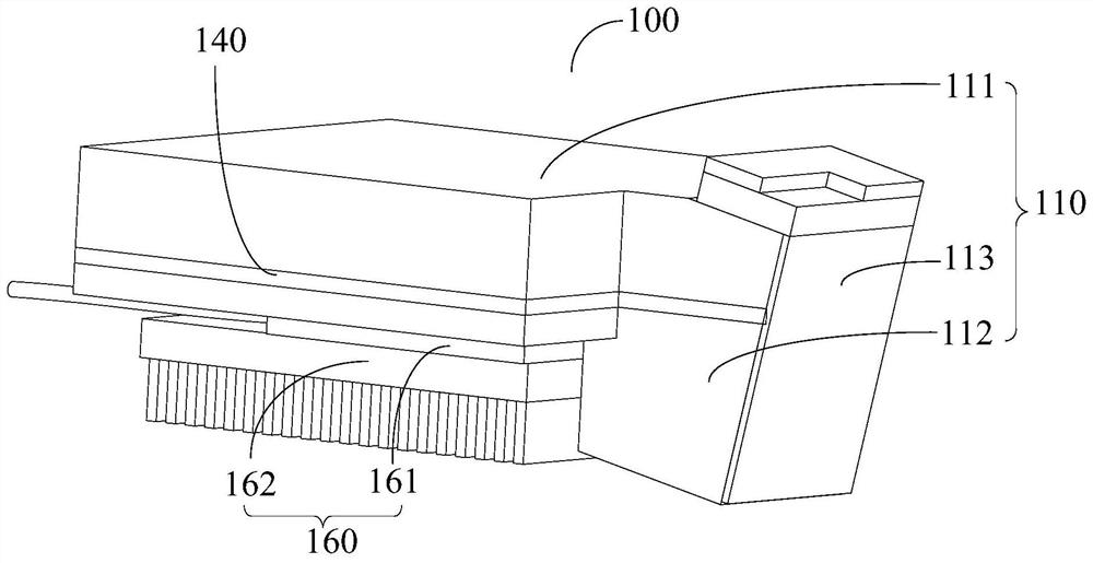
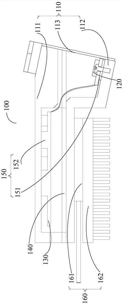
[0043] see Figure 1 to Figure 3 The present invention provides a detection device 100, which is arranged in a scanning system. In the present invention, the scanning system refers to a CT system, and the detection device 100 is used to detect radiation from a radiation source. In the present invention, the ray source refers to the tube, which emits X-rays. The detection device 100 of the present invention is used to detect the X-rays emitted by the tube of the CT system, so as to detect the ray intensity of the tube and track the focal position of...


PUM


Abstract

The present invention provides a detection device, comprising: a housing assembly having an accommodating chamber, and an incident window communicated with the accommodating chamber; a detection chip arranged in the accommodating chamber for detecting The rays passing through the incident window output electrical signals; the signal processing board is arranged in the accommodating chamber, the signal processing board is electrically connected to the detection chip, and is used to receive and process the output of the detection chip an electric signal; and a separation component, which is arranged on the housing component, and the signal processing board and the detection core are respectively located on two sides of the separation component. The separation part can separate the heat generated by the detection chip from the heat generated by the signal processing board on the shell assembly, reducing the coupling between heat sources, thereby ensuring that the temperature of the detection chip and the signal processing board will not rise, and ensuring that the detection device can Normal response, thereby ensuring the correction stability of the detection device and improving the image quality. The invention also provides a CT system.

Description

technical field [0001] The invention relates to the technical field of medical equipment, in particular to a CT system and a detection device thereof. Background technique [0002] At present, imaging equipment such as a CT machine usually emits X-rays to scan the human body through a ball tube, and receives and detects the X-rays through a detector. The focus position of the tube will shift during the scanning process, but if the original focus position data of the tube is still used in image reconstruction, it will cause image artifacts, which is not conducive to the doctor's diagnosis. Therefore, it is necessary to refer to the position of the tube focus by the detector. The position is detected, and after detection, the detector receives X-ray imaging, and the X-ray received by the detector is corrected by the reference detector to perform image imaging to ensure image quality. However, the superposition of heat generated by the reference detector during operation affec...

Claims


Application Information

Patent Timeline
Patent Type & Authority Patents(China)
IPC IPC(8): A61B6/03A61B6/00
CPCA61B6/035A61B6/4488
Inventor 叶婷
Owner SHANGHAI UNITED IMAGING HEALTHCARE
Learn More