
Three-dimensional software-based weldment modeling method

A 3D software and modeling method technology, applied in image data processing, special data processing applications, instruments, etc., can solve problems such as inaccurate drawing, low work efficiency, and difficulty in ensuring the correct size of parts, and achieve a wide range of applications. , high accuracy, and the effect of improving work efficiency

Active Publication Date: 2018-05-01
辽宁三三工业有限公司
View PDF5 Cites 2 Cited by
  • Summary
  • Abstract
  • Description
  • Claims
  • Application Information

AI Technical Summary

Problems solved by technology

The connection between the spoke and the base is mostly an intersecting structure. If you follow the traditional design method, use 3D software to model each part, and then assemble it, because each part has many intersecting lines, which are not on the same plane In fact, many 3D sketches or auxiliary datum planes need to be established during the drawing process, which requires relatively high modeling ability of the designer, and many spatial curves cannot be drawn accurately, which leads to very low work efficiency and very low It is difficult to ensure the correct size of each part

Method used


Image

  • Three-dimensional software-based weldment modeling method
  • Three-dimensional software-based weldment modeling method
  • Three-dimensional software-based weldment modeling method

Examples


Embodiment 1

[0036] The modeling process of all parts of the shield machine cutter body weldment is as follows:

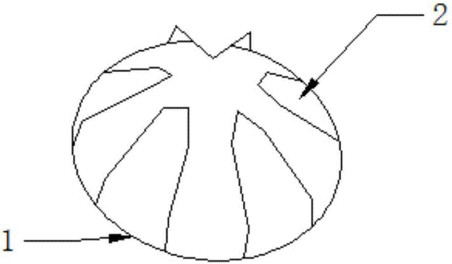
[0037] 1. Design the entire cutter body as one part, such as figure 1 As shown in , the three-dimensional model of the cutter body flange 2 and the base 1 is established first;

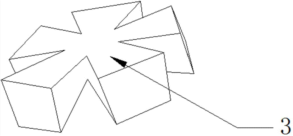
[0038] 2. If figure 2 As shown in Fig. 1, build a spoke box model other than the three-dimensional model of the cutter body flange and the base; insert the spoke box model into the base model part, position it constrainedly, and then use the Boolean operation method to combine it into one;

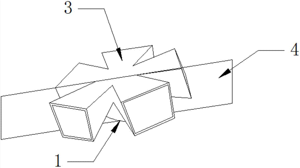
[0039] 3. If image 3 As shown in , select different surfaces according to the design requirements to extract the shell as a whole, and the thickness of the shell is divided according to the thickness of the plate;

[0040] 4. Establish the separation surface 4, and use the segmentation method to divide the whole part into spliced ​​parts of different sizes. Its characteristic is that it is still a whole part, ...


PUM


Abstract

The present invention provides a three-dimensional software-based weldment modeling method, and belongs to the field of welding modeling. The method comprises: step 1, drawing the finished weldment ina three-dimensional software into a part; step 2, establishing a segmentation plane, using a segmentation method to segment the entire part into spliced parts of different sizes, and carrying out chamfering on the connection of each spliced part; step 3, saving the parts completed in the step 2 as a file in an editable universal form that can be opened by multiple three-dimensional software; andstep 4, re-opening the file generated in the step 3 by using the 3D software to generate multiple features, wherein each feature corresponds to an independent spliced part in the step 2, and each feature is saved as a separate part illustration. According to the method provided by the present invention, the design time can be saved, the work efficiency can be improved, and the accuracy of the sizeof each dismantled welding part can be ensured to be 100%.

Description

technical field [0001] The invention belongs to the field of weldment modeling and relates to a welding modeling method based on three-dimensional software. Background technique [0002] Most of the large-diameter slurry shield machines are now in the form of normal pressure tool change. According to the process requirements, the cutter body should be designed as a box-shaped beam with a hollow structure. The connection between the spoke and the base is mostly an intersecting structure. If you follow the traditional design method, use 3D software to model each part, and then assemble it, because each part has many intersecting lines, which are not on the same plane In fact, many 3D sketches or auxiliary datum planes need to be established during the drawing process, which requires relatively high modeling ability of the designer, and many spatial curves cannot be drawn accurately, which leads to very low work efficiency and very low It is difficult to ensure the correct siz...

Claims


Application Information

Patent Timeline
IPC IPC(8): G06F17/50G06T19/20
CPCG06T19/20G06T2219/2008G06F30/17
Inventor 许彦平于丕杰
Owner 辽宁三三工业有限公司
Learn More