Pill polishing machine
A polishing machine and pill technology, which is applied in the field of machinery, can solve the problems of low working efficiency of polishing machine, easy breakage of pills or capsules, low breakage rate of working efficiency pills, etc. Effect
- Summary
- Abstract
- Description
- Claims
- Application Information
AI Technical Summary
Problems solved by technology
Method used
Image
Examples
Embodiment 1
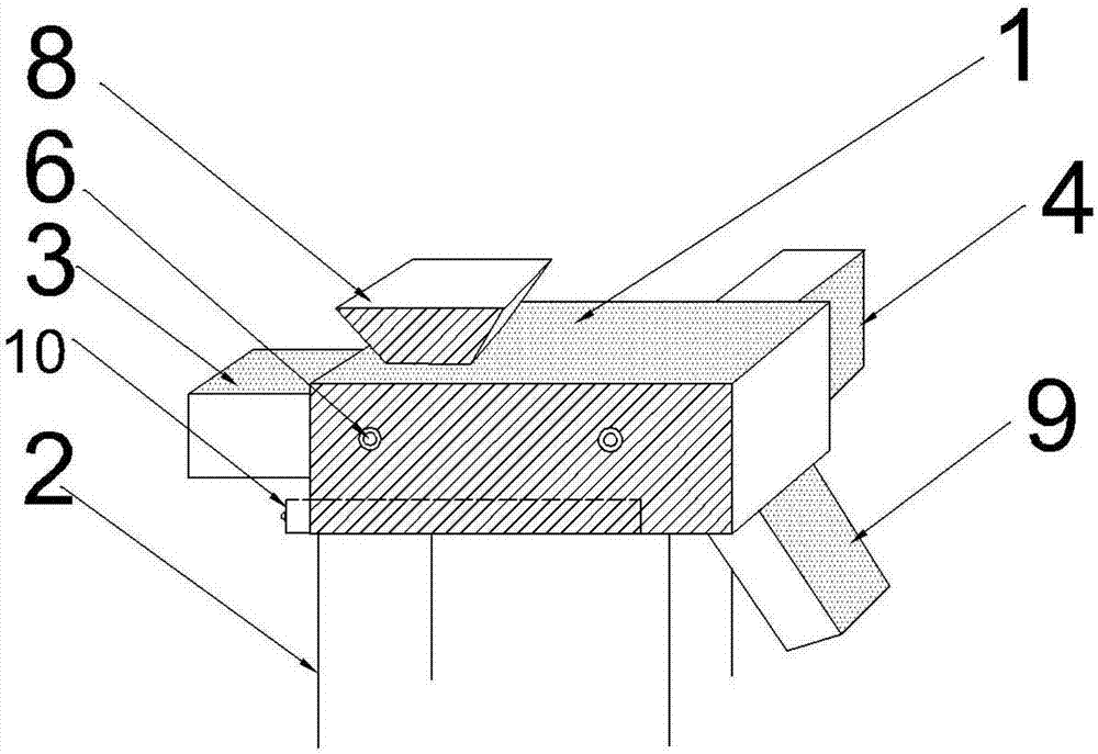
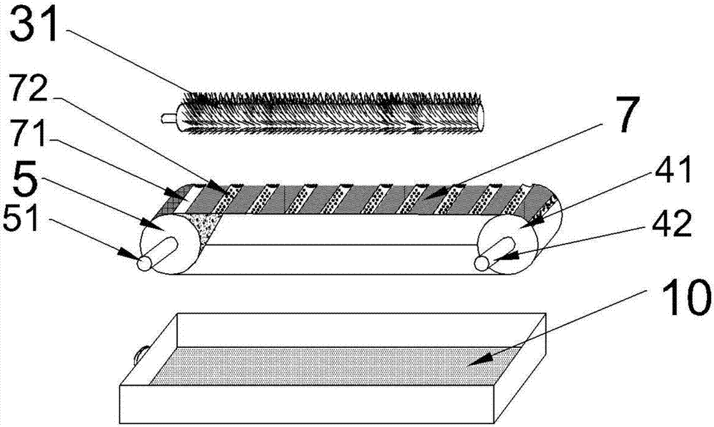
[0019] Embodiment 1 discloses a kind of pill polishing machine, as figure 1 and 2 As shown, it includes a housing 1 and a support frame 2, the housing 1 is fixedly installed on the top of the support frame 2, the upper end of the top of the housing 1 is also provided with a feed port (not marked in the figure), and the lower end of the tail of the housing 1 is provided with There is a discharge port (not marked in the figure). The pill polishing machine also includes a brush motor 3 and a roller motor 4. The brush motor 3 is fixedly installed on the top of the housing, and the roller motor 4 is fixedly installed on the side of the housing 1. part, the inner cavity of the housing 1 is also horizontally provided with a brush roller 31, and the brush roller 31 is fixedly connected with the brush motor 3;
[0020] The inner cavity of the housing 1 is also provided with a driving shaft roller 41 and a driven shaft roller 5 respectively, the driving shaft roller 41 and the driven s...
Embodiment 2
[0022] Embodiment 2 discloses a pill polishing machine, including a housing 1 and a support frame 2, the housing 1 is fixedly installed on the upper part of the support frame 2, and the upper end of the top of the housing 1 is also provided with a feed port (not marked in the figure) , the lower end of the tail of the housing 1 is provided with a discharge port (not marked in the figure), the pill polishing machine also includes a brush motor 3 and a roller motor 4, the brush motor 3 is fixedly installed on the top of the housing, and the roller motor 4 Fixedly installed on the side of the housing 1, the inner cavity of the housing 1 is also horizontally provided with a brush roller 31, and the brush roller 31 is fixedly connected to the brush motor 3;
[0023] The inner cavity of the housing 1 is also provided with a driving shaft roller 41 and a driven shaft roller 5 respectively, the driving shaft roller 41 and the driven shaft roller 5 are relatively horizontally arranged, ...
Embodiment 3
[0025] Embodiment 3 discloses a pill polishing machine, comprising a shell 1 and a support frame 2, the shell 1 is fixedly installed on the upper part of the support frame 2, the upper end of the top of the shell 1 is also provided with a feed port, and the tail of the shell 1 The lower end is provided with a discharge port. The pill polishing machine also includes a brush motor 3 and a roller motor 4. The brush motor 3 is fixedly installed on the top of the housing, and the roller motor 4 is fixedly installed on the side of the housing 1. The housing The inner cavity of 1 is also provided with a brush roller 31 horizontally, and the brush roller 31 is fixedly connected with the brush motor 3;
[0026] The inner cavity of the housing 1 is also provided with a driving shaft roller 41 and a driven shaft roller 5 respectively, the driving shaft roller 41 and the driven shaft roller 5 are relatively horizontally arranged, and the driving shaft roller 41 and the driven shaft roller ...
PUM
| Property | Measurement | Unit |
|---|---|---|
| Aperture | aaaaa | aaaaa |
Abstract
Description
Claims
Application Information
 - R&D
- Intellectual Property
- Life Sciences
- Materials
- Tech Scout
- Unparalleled Data Quality
- Higher Quality Content
- 60% Fewer Hallucinations
Browse by: Latest US Patents, China's latest patents, Technical Efficacy Thesaurus, Application Domain, Technology Topic, Popular Technical Reports.
© 2025 PatSnap. All rights reserved.Legal|Privacy policy|Modern Slavery Act Transparency Statement|Sitemap|About US| Contact US: help@patsnap.com


