Eureka AIR delivers breakthrough ideas for toughest innovation challenges, trusted by R&D personnel around the world.

Method and device for the adaptive regulation of a positive end-expiratory pressure (PEEP)

A technology of positive end-expiratory pressure and exhalation valve, which is applied in the direction of applications, respirators, and medical equipment, etc. It can solve the problems of affected expiratory flow, unmonitorable residual volume, and air retention, etc., and achieve rapid reduction of exhalation. The effect of airflow

Active Publication Date: 2018-05-01
DRAGERWERK AG
View PDF14 Cites 6 Cited by
  • Summary
  • Abstract
  • Description
  • Claims
  • Application Information

AI Technical Summary

Problems solved by technology

Air trapping cannot be avoided with this method either, since the remaining volume in the lungs cannot be monitored during exhalation
[0007] In known installations, the expiratory flow cannot usually be influenced during the exhalation phase because the exhalation valve and sensor are separated from the patient by the long airway
Changes in airflow are therefore only delayed or attenuated through the airway so that measurements of expiratory parameters cannot be achieved simultaneously with changes in PEEP

Method used

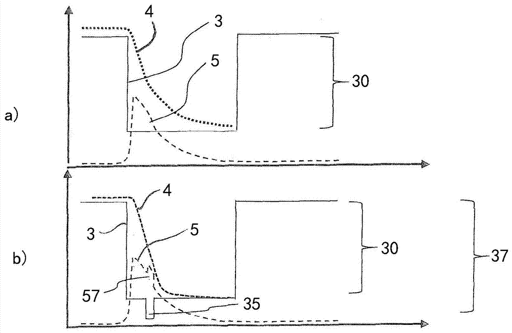
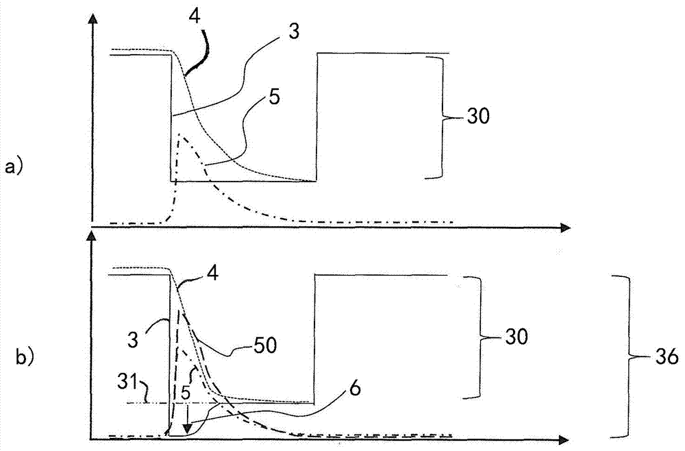
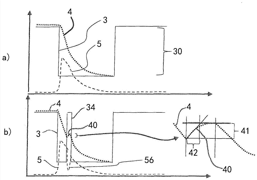

Image

  • Method and device for the adaptive regulation of a positive end-expiratory pressure (PEEP)
  • Method and device for the adaptive regulation of a positive end-expiratory pressure (PEEP)
  • Method and device for the adaptive regulation of a positive end-expiratory pressure (PEEP)

Examples


Embodiment Construction

[0028] Respiratory facilities in their entirety are figure 1 Indicated by reference numeral 1. It has a blower unit 10 with a fan 17 , which is connected to the patient 2 via a user interface 16 .

[0029] The user interface 16 here consists of a tube 13 connected to the air flow measuring unit 14 , a Y-piece 15 connected at one end to the air flow measuring unit 14 , and an exhalation valve 11 connected to the second end of the Y-piece 15 . The last end of the Y-shaped piece 15 is fluidically connected via a hose 12 to a fan 17 of the blower unit 10 .

[0030] Alternatively, the user interface 16 can be designed as a face mask, as a nasal mask or also in another form, wherein the user interface 16 accordingly includes the exhalation valve 11 .

[0031] Furthermore, the breathing apparatus 1 comprises a control device 18 , which transmits control signals to the exhalation valve 11 and the fan 17 and receives measurement signals from the air flow measuring unit 14 . The cont...


PUM


Abstract

A method controls an expiratory gas flow at a user interface (16) of a ventilator (1) wherein the user interface (16) has an exhalation valve (11), which provides a positive end-expiratory pressure (PEEP). The method includes the following steps during a phase of exhalation: changing the positive end-expiratory pressure from a basic PEEP value (31) with the exhalation valve (11); returning the positive end-expiratory pressure to the basic PEEP value (31) with the exhalation valve (11); and determining an exhalation parameter. The method permits an adaptive change in the expiratory flow duringthe exhalation. Air trapping can be avoided, and it is possible to respond to changed exhalation parameters within one and the same phase of exhalation.

Description

technical field [0001] The present invention relates to a method for controlling the flow of expiratory air. Background technique [0002] Use of respiratory equipment to assist the patient's breathing. In this case, the breathing apparatus introduces breathing air into the patient's lungs and also removes the air from the lungs, for example during forced respiration. In order not to damage the patient's lungs, certain parameters of the lungs and the tube system used must be known to the breathing apparatus with which the breathing air is conveyed from the apparatus to the patient and, if necessary, back. In this case, the aerodynamic resistance on the facility side, the compliance of the facility, the compliance of the lungs and the airway resistance are taken into account, if applicable. [0003] In order to avoid collapse of the lungs during the exhalation phase, the positive end-expiratory pressure (PEEP) is adjusted by means of an exhalation valve, which defines the m...

Claims


Application Information

Patent Timeline
Patent Type & Authority Applications(China)
IPC IPC(8): A61M16/00A61B5/08
CPCA61M16/0003A61B5/08A61M2205/33A61B5/087A61M2016/0036A61M2230/46A61M16/0833A61M16/205A61M2016/0027A61M2230/005A61M16/0009A61B5/091A61M16/18A61M16/20A61M16/22A61M2016/0021A61M2016/003A61M2016/0039A61M2016/0042A61M2016/0413
Inventor H-U.汉斯曼K.希尔塔夫斯基
Owner DRAGERWERK AG
Why Eureka
Eureka Blog
Learn More