
Corner streamhandling method for double-layer injection molding of LED light-guide components

A light guide component and double-layer injection molding technology, applied in the field of automobile lamp manufacturing, can solve problems such as low pass rate, affecting product molding quality, and inability to discharge

Active Publication Date: 2015-06-10
HASCO VISION TECHNOLOGY CO LTD
View PDF5 Cites 2 Cited by
  • Summary
  • Abstract
  • Description
  • Claims
  • Application Information

AI Technical Summary

Problems solved by technology

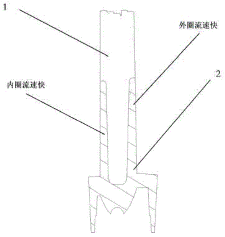
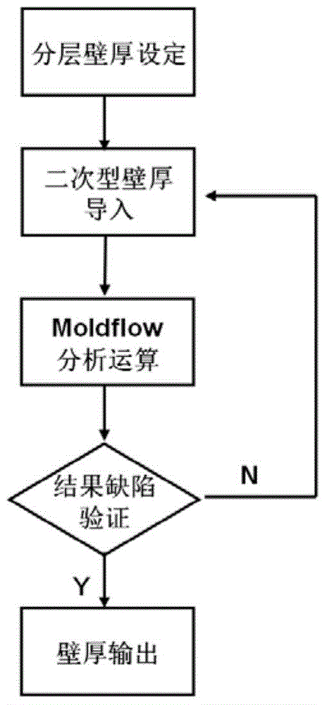
According to the present invention, with the help of CAE software, the layered wall thickness can be effectively guided to provide a more reasonable layered method, thereby solving the problem caused by the residual gas that cannot be discharged from the mold cavity due to the difference in plastic flow rate during the injection molding process. Trapped air defects and the molding quality of products affected by them, and low pass rate

Method used


Image

  • Corner streamhandling method for double-layer injection molding of LED light-guide components
  • Corner streamhandling method for double-layer injection molding of LED light-guide components
  • Corner streamhandling method for double-layer injection molding of LED light-guide components

Examples


Embodiment

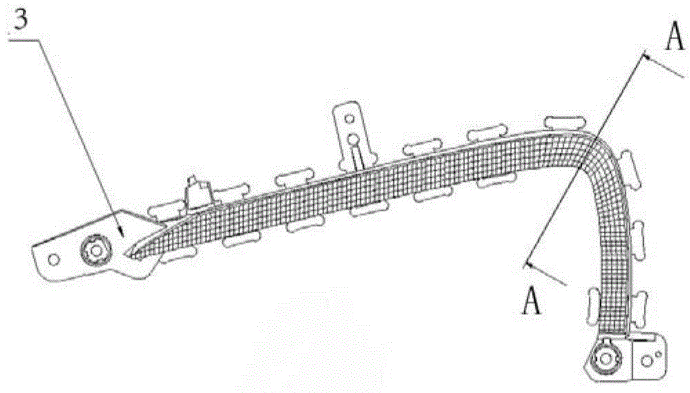
[0062] A corner flow treatment method for double-layer injection molding of an LED light guide component uses a double-layer injection mold that is divided into two injection moldings and is used for injection molding thick-walled light guide components. The thick-walled light guide member is composed of a "convex" section of the product and a "concave" section matching the "convex" section.

[0063] The double-layer injection mold includes a “convex” primary injection cavity portion corresponding to the cross-sectional shape of the product and a secondary injection cavity portion with a “concave” cross-sectional shape, that is, the primary injection cavity is used for Forming the "convex" portion of the light guiding member, the overmolded cavity is used to form a "female" portion that mates with the "convex" portion of the light guiding member. The secondary injection molding cavity is used to form the wall thickness of the cavity between the inner and outer sides of the "co...


PUM


Abstract

The invention discloses a corner streamhandling method for the double-layer injection molding of LED light-guide components. According to the method, a double-layer injection mold for carrying out injection molding on thick-walled light-guide components is adopted, and comprises a primary injection mold cavity part and a secondary injection mold cavity part which are respectively in the shape of a Chinese character 'tu' corresponding to the shape of the cross section of a product and in the shape of a Chinese character 'ao' corresponding to the shape of the cross section of the product. The method is characterized by comprising the following steps: setting a basic mold cavity wall thickness between the inner side and outer side of a portion, for forming the part in the shape of a Chinese character 'ao' at a corner of a light-guide component, of the secondary injection mold cavity; carrying out wall thickness compensation adjustment: the wall thickness difference is sequentially increased, i.e. the wall thickness of the outside cavity, for forming the part in the shape of a Chinese character 'ao' at the corner of the light-guide component, of the secondary injection mold cavity is increased by 0.1-0.3 mm, and the wall thickness of the inside cavity of the secondary injection mold cavity is correspondingly reduced by 0.1-0.3 mm; and respectively gradually increasing and reducing the curvatures of the inner side and outer side of a portion formed at the corner of the light-guide component, of the secondary injection mold cavity, so that the flow speed of an injection molding fluid flowing through the corner of the secondary injection mold cavity and reaching a vehicle headlight is consistent, and a defect of air trapping does not occur in the process of injection molding.

Description

Technical field: [0001] The invention relates to the field of automobile lamp manufacturing, in particular to a double-layer injection molding layered light guide corner processing method used for corner treatment in the thick-wall layered light guide injection molding process of LED light guide components. Background technique: [0002] Since the birth of automobiles at the end of the nineteenth century, car lights have also undergone generation after generation of changes, from the first generation of fuel-burning light sources; the second generation of incandescent light sources; the third generation of gas discharge light sources to the fourth generation of semiconductor light sources Diode (ie LED) light source. And with the continuous update of LED technology and the continuous improvement of people's requirements for the appearance of car lights, the derivative technology of LED - light guide technology has been born. [0003] Light guides used in automotive lighting...

Claims


Application Information

Patent Timeline
IPC IPC(8): B29C45/37B29C45/16B29C45/80B29C45/17
Inventor 徐超王昌威
Owner HASCO VISION TECHNOLOGY CO LTD
Learn More