
Motor fan applied to air compressor

A technology using a motor and an air compressor, applied in the field of machinery, can solve the problems of reduced motor efficiency and high fan energy consumption, and achieve the effects of improving efficiency, large air output, and reducing manufacturing costs.

Inactive Publication Date: 2018-04-27
陈雪女
View PDF0 Cites 1 Cited by
  • Summary
  • Abstract
  • Description
  • Claims
  • Application Information

AI Technical Summary

Problems solved by technology

At present, the heat dissipation fan of the motor used in the direct-coupled air compressor also adopts the structure of the fan blade of the motor in the past. The blade is straight and the direction of the blade is perpendicular to the motor shaft. The wind generated by the fan is small. In order to meet the heat dissipation requirements of the motor, the outer diameter of the fan is increased during design, but the energy consumption of the fan is large when it is working, resulting in a decrease in the efficiency of the motor

Method used


Image

  • Motor fan applied to air compressor
  • Motor fan applied to air compressor

Examples


Embodiment Construction

[0016] The following are specific embodiments of the present invention and in conjunction with the accompanying drawings, the technical solutions of the present invention are further described, but the present invention is not limited to these embodiments.

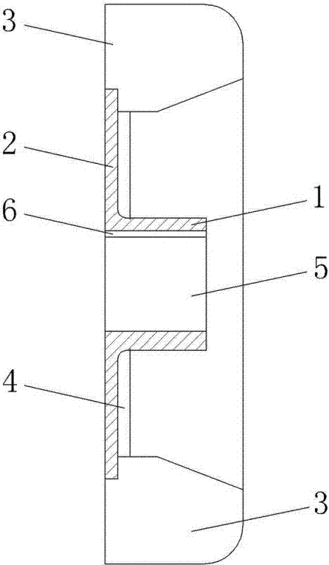
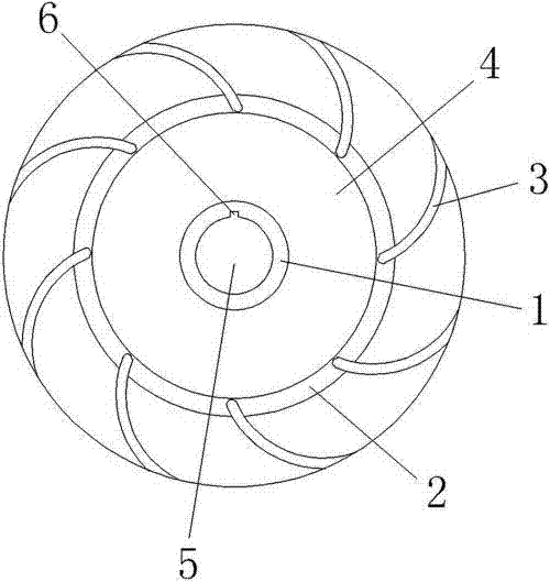
[0017] Such as figure 1 The shown motor fan for an air compressor includes a hub 1 for connecting with the motor shaft, a cover plate 2 arranged at the end of the hub 1 and a blade 3 arranged on the cover plate 2, the cover plate 2 is circular and The hub 1 is coaxially arranged, and the blades 3 are several and evenly distributed on the cover plate 2, and the blades 3 are vertically arranged on the side of the cover plate 2 close to the hub 1, such as figure 2 As shown, the blade 3 spirally extends outward with the hub 1 as the center, and the spiral extension direction of the blade 3 is the same as the rotation direction of the motor shaft.

[0018] As we all know, the fixed rotation direction of the main shaft has bee...


PUM


Abstract

The invention provides a motor fan for an air compressor, which belongs to the technical field of machinery. It solves the problem that the existing motor fan has straight blades, which has high power consumption and low efficiency. The air compressor motor fan includes a hub used to connect with the motor shaft, a cover plate arranged at the end of the hub and blades arranged on the cover plate, the cover plate is circular and coaxially arranged with the hub, and the blades are several and evenly distributed on the cover plate. The blades are vertically arranged on the side of the cover plate close to the hub. The blades spirally extend outward with the hub as the center. The spiral extension direction of the blades is the same as the rotation direction of the motor shaft. The invention has the advantages of low energy consumption, large air volume, high efficiency and the like.

Description

technical field [0001] The invention belongs to the technical field of machinery, and relates to a cooling fan for a motor, in particular to a motor fan for a direct-connected air compressor. Background technique [0002] In the past, in the design process of the motor, considering that the motor can rotate forward and reverse, the blades are designed as straight blades to ensure that the motor can generate air volume no matter whether the motor rotates clockwise or counterclockwise, so as to achieve the function of cooling the motor. At present, the heat dissipation fan of the motor used in the direct-coupled air compressor also adopts the structure of the fan blade of the motor in the past. The blade is straight and the direction of the blade is perpendicular to the motor shaft. The wind generated by the fan is small. In order to meet the heat dissipation requirements of the motor, the outer diameter of the fan is increased during design, but this results in a large energy...

Claims


Application Information

Patent Timeline
Patent Type & Authority Applications(China)
IPC IPC(8): F04B39/06F04D29/28
CPCF04B39/066F04D29/281
Inventor 吴良
Owner 陈雪女
Learn More