a composite floor
A composite and floor technology, applied in the direction of buildings, floors, insulation layers, etc., can solve the problems of glue opening and deformation, damage to the ecological environment, and high production costs, and achieve the effects of eliminating internal stress, expanding the bonding area, and reducing weight
- Summary
- Abstract
- Description
- Claims
- Application Information
AI Technical Summary
Problems solved by technology
Method used
Image


Examples
Embodiment 1
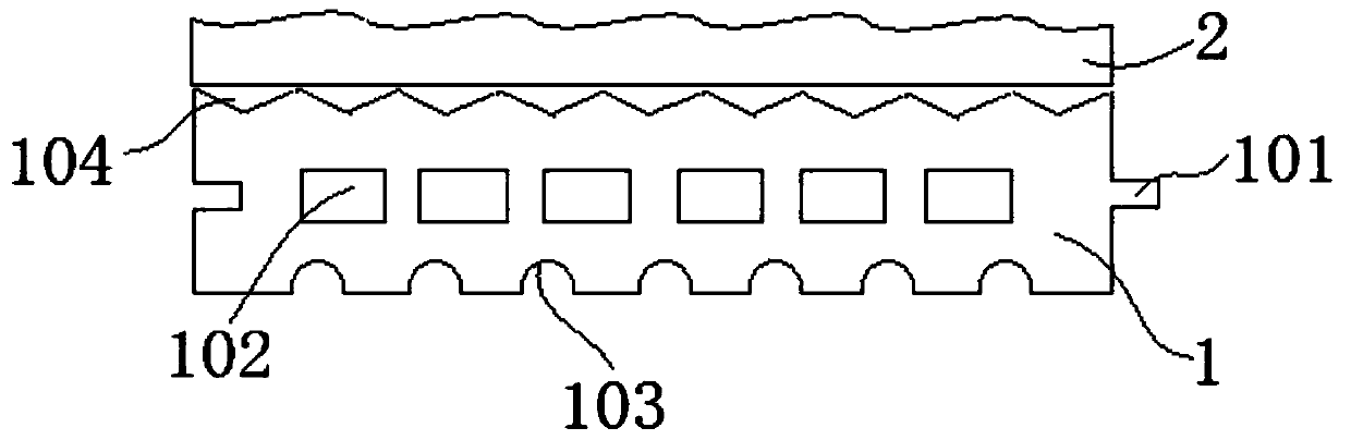
[0040] combine figure 1 , The composite floor of this embodiment is formed by bonding the panel 2 of the upper layer and the substrate 1 of the lower layer, the panel 2 is a solid wood board, and the substrate 1 is a PVC stone-plastic board. The upper surface of the panel 2 is an irregular wear-resistant surface with concave-convex patterns, and the top of the wear-resistant surface with concave-convex patterns is covered with a paint layer. The thickness of the substrate 1 is greater than that of the panel 2 . The upper surface of the substrate 1 is provided with a substrate glue storage tank 104 along the length direction. The substrate glue storage groove 104 is a groove with a V-shaped cross section. The substrate glue storage grooves 104 are adjacently arranged continuously along the width direction of the substrate 1. The two edges along the length direction of the substrate 1 are symmetrically provided with mutually inserted notch and protrusion structures 101 , and th...
Embodiment 2
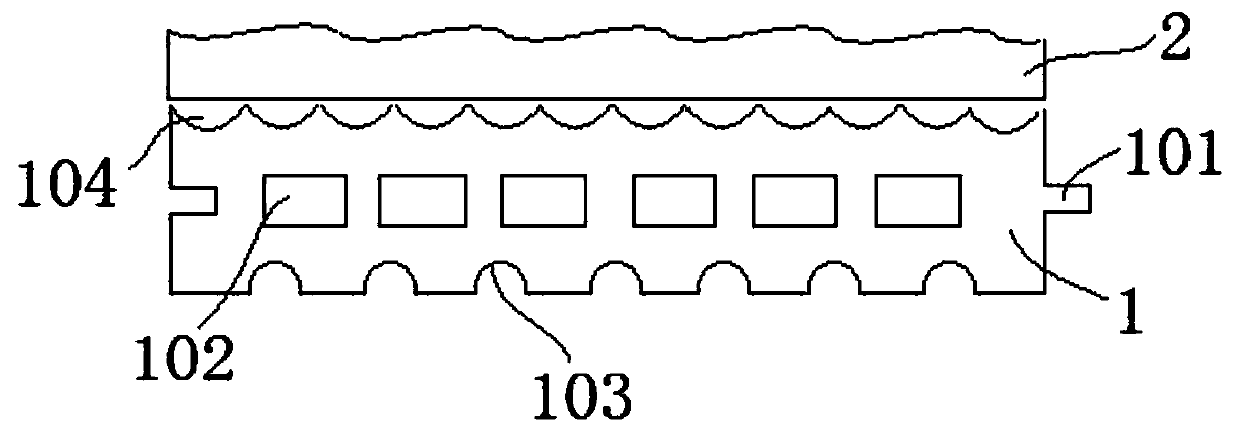
[0050] combine figure 2 , The composite floor of this embodiment is formed by bonding the panel 2 of the upper layer and the substrate 1 of the lower layer, the panel 2 is a solid wood board, and the substrate 1 is a PVC stone-plastic board. The upper surface of the panel 2 is an irregular wear-resistant surface with concave-convex patterns, and the top of the wear-resistant surface with concave-convex patterns is covered with a paint layer. The thickness of the substrate 1 is greater than that of the panel 2 . The upper surface of the substrate 1 is provided with a substrate glue storage tank 104 along the length direction. The substrate glue storage groove 104 is a groove with an arc-shaped cross section. The substrate glue storage grooves 104 are adjacently arranged continuously along the width direction of the substrate 1. The two edges along the length direction of the substrate 1 are symmetrically provided with mutually inserted notch and protrusion structures 101 , an...
Embodiment 3
[0052] combine image 3 , The composite floor of this embodiment is formed by bonding the panel 2 of the upper layer and the substrate 1 of the lower layer, the panel 2 is a solid wood board, and the substrate 1 is a PVC stone-plastic board. The upper surface of the panel 2 is an irregular wear-resistant surface with concave-convex patterns, and the top of the wear-resistant surface with concave-convex patterns is covered with a paint layer. The lower surface of the panel 2 is provided with a panel glue storage tank 201 along the length direction. The panel glue storage tank 201 is a groove with a V-shaped cross section. The thickness of the substrate 1 is greater than that of the panel 2 . The two edges along the length direction of the substrate 1 are symmetrically provided with mutually inserted notch and protrusion structures 101 , and the two edges of the substrate 1 along the width direction are also symmetrically provided with mutually inserted notch and protrusion str...
PUM
 Abstract
Description
Claims
Application Information
 - R&D
- Intellectual Property
- Life Sciences
- Materials
- Tech Scout
- Unparalleled Data Quality
- Higher Quality Content
- 60% Fewer Hallucinations
Browse by: Latest US Patents, China's latest patents, Technical Efficacy Thesaurus, Application Domain, Technology Topic, Popular Technical Reports.
© 2025 PatSnap. All rights reserved.Legal|Privacy policy|Modern Slavery Act Transparency Statement|Sitemap|About US| Contact US: help@patsnap.com