
Diversion structure, mixed flow fan and range hood

A mixed-flow fan and range hood technology, which is applied in the direction of removing oil fume, machines/engines, and mechanical equipment, etc., can solve the problems of reducing the exhaust air volume of the range hood, high power consumption of the centrifugal fan, and low air pressure, and achieve the effect of exhausting oil fume. The effect of a good, good cooking environment

Active Publication Date: 2020-06-19
GREE ELECTRIC APPLIANCES INC
View PDF5 Cites 0 Cited by
  • Summary
  • Abstract
  • Description
  • Claims
  • Application Information

AI Technical Summary

Problems solved by technology

[0002] Most of the existing range hoods use centrifugal fans. The power consumption of centrifugal fans is high, but the wind pressure generated is low. If range hoods with centrifugal fans are used in high-rise buildings, and the operating time When the section is concentrated, the resistance in the public flue is too large, resulting in a sharp decrease in the exhaust air volume of the range hood, and the adsorption effect on the cooking fume in the kitchen is weakened, and the cooking fume cannot be effectively discharged
[0003] In addition, the shape of the diversion structure inside the range hood is relatively regular. When using the range hood, the air flow rate mixed with the oil fume is slow, and the oil fume in the kitchen cannot be quickly sucked away. Irreversible damage, poor user experience

Method used


Image

  • Diversion structure, mixed flow fan and range hood
  • Diversion structure, mixed flow fan and range hood
  • Diversion structure, mixed flow fan and range hood

Examples


Embodiment Construction

[0028] The present invention is described below based on the embodiments, and those skilled in the art should understand that the drawings provided here are for the purpose of illustration, and the drawings are not necessarily drawn to scale.

[0029] Unless the context clearly requires, throughout the specification and claims, "comprises", "comprises" and similar words should be interpreted in an inclusive sense rather than an exclusive or exhaustive meaning; that is, "including but not limited to" meaning.

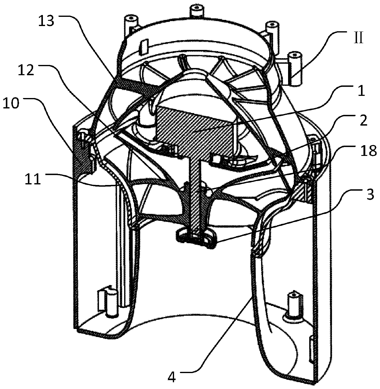
[0030] The above and below described in this application specification Figure 5 The orientation shown in the Figure 5 The up and down directions shown in are respectively the up and down directions in this application, and the cross section in this application refers to the Figure 5 The vertical section in the vertical direction.

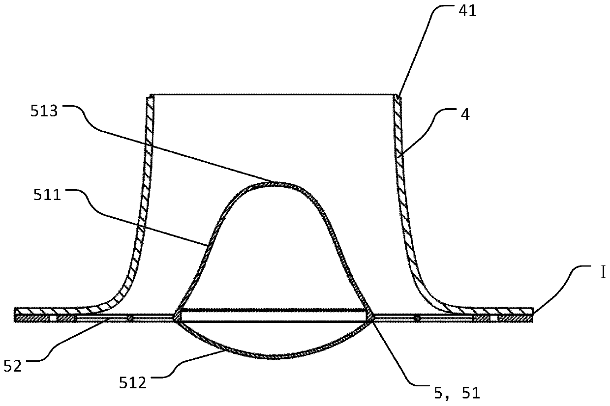
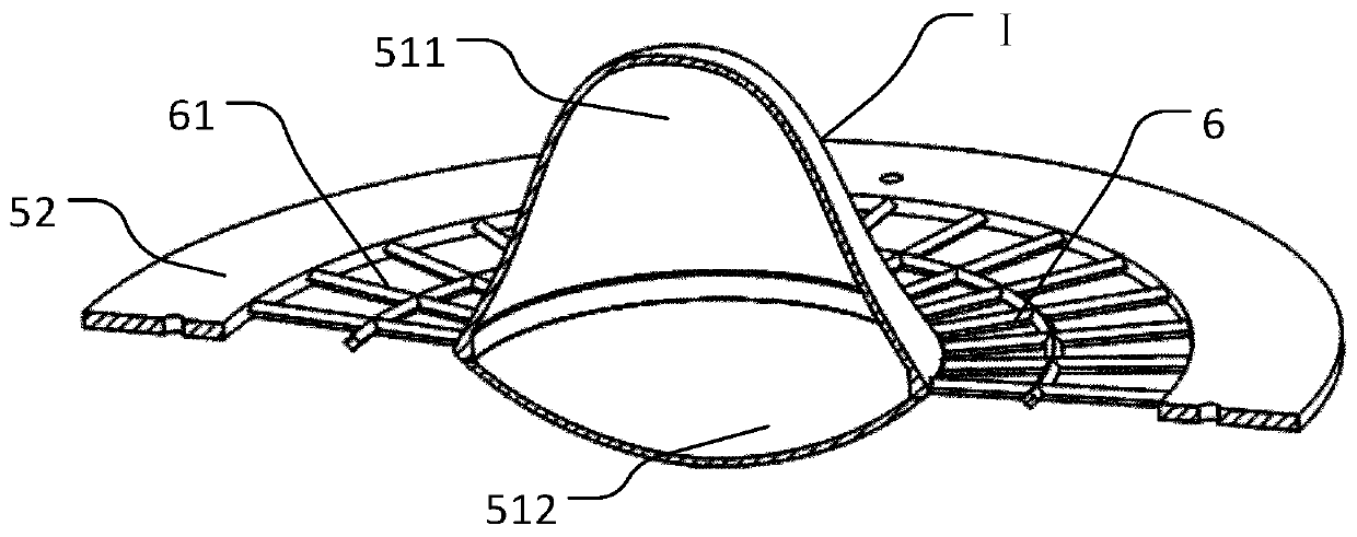
[0031] Such as figure 1 , figure 2 , Figure 5 As shown, the flow guide structure I provided by the present application includes a ...


PUM


Abstract

The invention provides a flow guiding structure, a mixed flow blower and an exhaust hood. The flow guiding structure is arranged on the air inlet side of the blower and comprises a flow guiding sleeveand a flow guiding piece arranged on the flow guiding sleeve, at least part of the structure of the flow guiding piece is located in the flow guiding sleeve, and an inner air flow channel is formed between the flow guiding sleeve and the flow guiding piece. The air flow channel communicates with an air inlet of the blower, an air inlet of the flow guiding structure is formed in the flow guiding piece, and the flow guiding piece and the flow guiding sleeve are connected in the circumferential direction of the flow guiding sleeve. The flow guiding structure is internally provided with a structure capable of generating the Venturi effect, and when an air flow flows into the flow guiding structure, the air flow speeds up to flow under the influence of the Venturi effect.

Description

technical field [0001] The invention relates to the field of kitchen appliances, in particular to a diversion structure, a mixed flow fan and a range hood. Background technique [0002] Most of the existing range hoods use centrifugal fans. The power consumption of the centrifugal fans is relatively high, but the wind pressure generated is relatively low. When the section is concentrated, the resistance in the public flue is too large, resulting in a sharp decrease in the exhaust air volume of the range hood, weakening the adsorption effect on the cooking fume in the kitchen, and the cooking fume cannot be effectively discharged. [0003] In addition, the shape of the diversion structure inside the range hood is relatively regular. When using the range hood, the air flow rate mixed with the lampblack is slow, and the lampblack in the kitchen cannot be sucked away quickly. The user has been in an environment full of lampblack for a long time, and the Suffering irreversible d...

Claims


Application Information

Patent Timeline
Patent Type & Authority Patents(China)
IPC IPC(8): F04D29/40F04D23/00F04D29/70F24C15/20
CPCF04D23/00F04D29/403F04D29/703F24C15/20
Inventor 邓志敏李思成王宏张建平张皓坤丁泺火
Owner GREE ELECTRIC APPLIANCES INC
Learn More