Oil filling barrel of drilling tool protective agent

A technology of protecting agent and refueling barrel, which is applied in the direction of preventing repeated filling of containers, closing, packaging, etc., can solve problems such as waste of resources, and achieve the effect of saving oil resources and having a simple structure.

Inactive Publication Date: 2018-04-24
CHONGQING LONGJIAN METAL MFG
View PDF0 Cites 0 Cited by
  • Summary
  • Abstract
  • Description
  • Claims
  • Application Information

AI Technical Summary

Problems solved by technology

[0002] The structure of the currently used refueling barrels is very simple. Its structure mainly includes a barrel body. An oil outlet pipe is arranged obliquely on the left side wall of the barrel body. The oil outlet pipe is arranged high on the left and low on the right. The walls are connected and communicated; when in use, after adding oil, a small part of oil will flow out from the nozzle of the oil outlet pipe every time. If there is too much oil left in the barrel, the oil flowing out from the nozzle will also increase. Unnecessary waste of resources due to multiple aspects

Method used


Image

  • Oil filling barrel of drilling tool protective agent

Examples


Embodiment

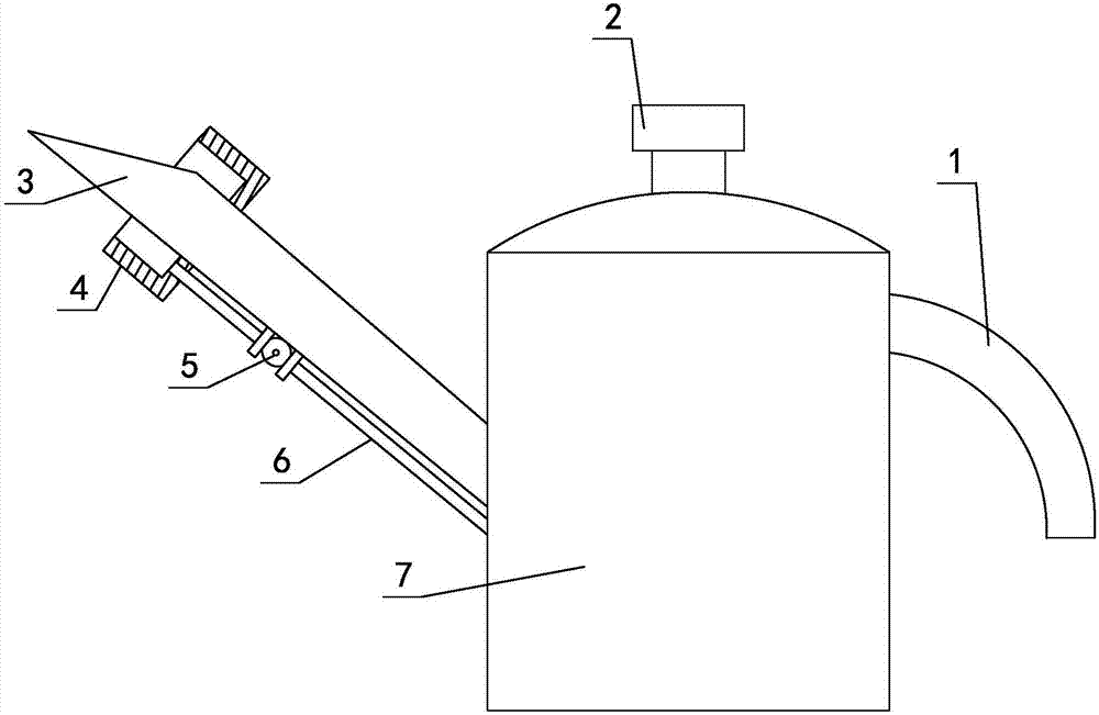
[0014] Such as figure 1 As shown, the refueling barrel of the drilling tool protective agent includes a barrel body 7, and an oil outlet pipe is arranged obliquely on the left side wall of the barrel body 7. The side walls are connected and communicated. A collection tank 4 is provided at the fuel nozzle 3 near the oil outlet pipe. The bottom of the collection tank 4 is provided with a through hole. The oil outlet pipe is installed in the through hole and is sealed and fixed. The bottom is connected with a refueling pipe 6; one end of the refueling pipe 6 is connected to the collection tank 4, and the other end is connected to the barrel body 7; a check valve 5 is installed on the refueling pipe 6, and the check valve 5 is used to prevent the The oil flows out from the filler pipe 6.

[0015] In this embodiment, the top of the bucket body 7 is provided with a bucket lid 2 which is fastened therewith; the right side wall of the bucket body 7 is provided with a handle 1 .

[0...


PUM


Abstract

The invention relates to a refueling barrel for a drilling tool protection agent, which belongs to the technical field of refueling barrels, and comprises a barrel body. An oil outlet pipe is arranged obliquely on the left side wall of the barrel body. The oil outlet pipe is arranged higher on the left and lower on the right. The lower left side wall of the body is connected and communicated. A collection tank is arranged near the oil nozzle of the oil outlet pipe. A through hole is opened at the bottom of the collection tank. The oil outlet pipe is installed in the through hole and is sealed and fixed. A fueling pipe is connected; one end of the fueling pipe is connected to the collection tank, and the other end is connected to the barrel; a check valve is installed on the fueling pipe, and the check valve is used to prevent the oil in the barrel from flowing out of the fueling pipe. The refueling barrel of the drilling tool protective agent according to the present invention has a simple structure. When in use, under the design of the collection tank, the oil flowing out of the filler nozzle will flow into the collection tank along the wall of the refueling pipe. to the barrel, effectively saving oil resources.

Description

technical field [0001] The invention relates to a refueling barrel for drilling tool protection agent, belonging to the technical field of refueling barrels. Background technique [0002] The structure of the currently used refueling barrels is very simple. Its structure mainly includes a barrel body. An oil outlet pipe is arranged obliquely on the left side wall of the barrel body. The oil outlet pipe is arranged high on the left and low on the right. The walls are connected and communicated; when in use, after adding oil, a small part of oil will flow out from the nozzle of the oil outlet pipe every time. If there is too much oil left in the barrel, the oil flowing out from the nozzle will also increase. Multiple aspects cause unnecessary waste of resources. Contents of the invention [0003] Based on the above deficiencies in the prior art, the technical problem to be solved by the present invention is to provide a refueling barrel for drilling tool protection agent, w...

Claims


Application Information

Patent Timeline
Patent Type & Authority Applications(China)
IPC IPC(8): B65D47/06B65D47/40B65D49/02
CPCB65D47/06B65D47/40B65D49/02
Inventor 秦秉宏
Owner CHONGQING LONGJIAN METAL MFG
Why Eureka
Try Eureka