A gpu card fixing structure suitable for 2u servers

A GPU card and fixed structure technology, which is applied in the field of GPU card fixed structure, can solve the problems of not being able to realize the function of multiple GPU cards, the installation density is not easy to be too high, and there is no core competitiveness, so as to reduce signal interference, reduce heat dissipation obstacles, and improve The Effect of Brand Competitiveness and Customer Satisfaction

Active Publication Date: 2021-05-25
ZHENGZHOU YUNHAI INFORMATION TECH CO LTD
View PDF7 Cites 0 Cited by
  • Summary
  • Abstract
  • Description
  • Claims
  • Application Information

AI Technical Summary

Problems solved by technology

However, limited by the height of the 2U server, only one layer of GPU cards can be installed even so, and since the GPU card of the 2U server is directly installed on the main board through the adapter board, it is necessary to avoid the components on the main board and install The density is not too high
Therefore, the 2U machine cannot realize the multi-GPU card function, resulting in insufficient product selling points and no core competitiveness.

Method used


Image

  • A gpu card fixing structure suitable for 2u servers
  • A gpu card fixing structure suitable for 2u servers
  • A gpu card fixing structure suitable for 2u servers

Examples


Embodiment 1

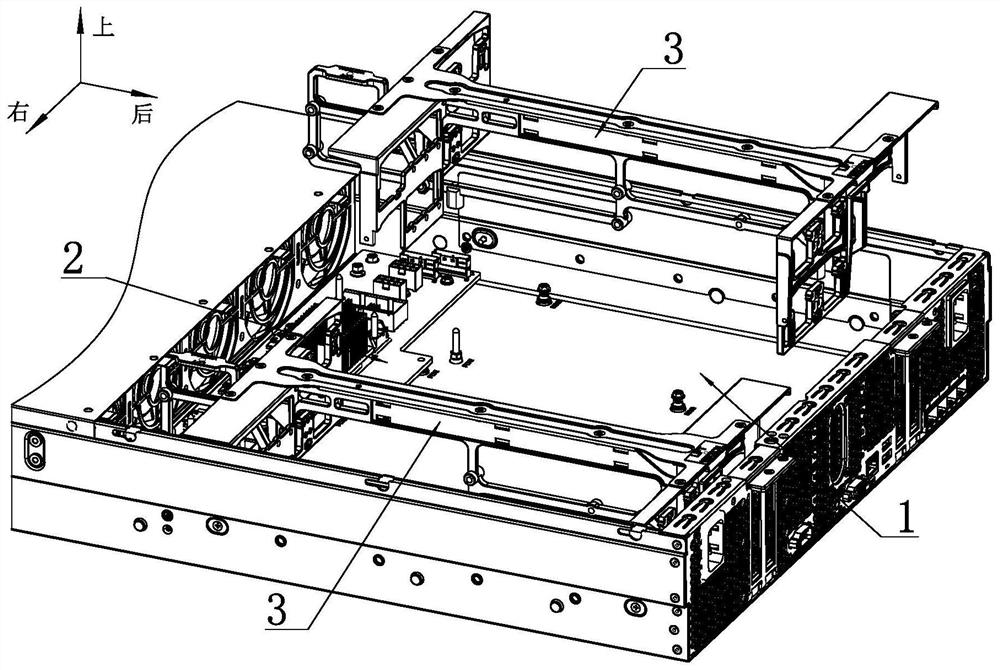
[0037] Such as figure 1 As shown, a GPU card fixing structure suitable for a 2U server includes a bracket assembly 3 arranged on the bottom plate of the chassis 1 . As a specific implementation manner, the number of the bracket assemblies 3 in this embodiment is two groups, and they are arranged along the left and right directions.

[0038] Such as Figure 4 and Figure 12 As shown, the bracket assembly 3 includes a main fixing plate 31, and the left and right sides of the main fixing plate 31 are respectively provided with a left adapter plate 4 and an adapter plate.

[0039] Such as Figure 9 and Figure 11 As shown, the rear end of the inner surface of the left adapter plate 4 (with the left adapter plate 4 and the opposite side of the adapter plate as the inner side) is provided with several left GPU plugs 42 along the vertical direction. As a specific implementation manner, the number of left GPU plugs 42 in this embodiment is two. The rear portion of the main fixin...

Embodiment 2

[0051] A plurality of left GPU plugs 42 are arranged vertically on the rear end of the inner surface of the left adapter plate 4 (the side opposite to the left adapter plate 4 and the adapter plate is the inner side). A number of right GPU plugs 52 are vertically arranged on the front end of the inner surface of the right adapter plate 5 (with the side opposite to the left adapter plate 4 and the adapter plate as the inner side).

[0052] The rear parts of the main fixing plate 31 and the right adapter plate 5 are respectively provided with a second through hole 312 and a fourth through hole allowing the left GPU plug 42 to pass through, and the left GPU plug 42 is connected from the left To the right, it passes through the main fixing plate 31 and the right adapter plate 5 to protrude from the right side of the right adapter plate 5 . The front parts of the main fixing plate 31 and the left adapter plate 4 are respectively provided with a first through hole 311 and a third th...


PUM


Abstract

The invention discloses a GPU card fixing structure suitable for a 2U server. The fixing structure is provided with a main fixing plate on the chassis bottom plate. Take board. A left GPU plug and a right GPU plug are respectively provided on the inside surfaces of the left adapter board and the right adapter board, and the left GPU plug protrudes to the left from the right side of the right adapter board, and the The right GPU plug protrudes leftward from the left side of the left adapter board, and the left GPU plug and the right GPU plug are respectively plugged with GPU cards. The front ends of the outer surfaces of the left adapter board and the right adapter board are respectively provided with a left adapter board plug and a right adapter board plug, and a left adapter board plug is fixedly arranged on the GPU board on the chassis bottom plate. slot and the right adapter board slot, the GPU board is connected with the main board through a cable. This fixed structure increases the number of GPU cards in the same space, increases product function requirements, and improves brand competitiveness and customer satisfaction.

Description

technical field [0001] The invention relates to the technical field of computer hardware equipment, in particular to a GPU card fixing structure suitable for 2U servers. Background technique [0002] U is a unit that indicates the external size of the server, and is an abbreviation of unit. The detailed size is determined by the Electronic Industries Association (EIA), which is an industry group. The specified size is the width (48.26cm=19 inches) and height (multiple of 4.445cm) of the server, and the basic unit of thickness is 4.445cm. 1U is 4.445cm, and 2U is 8.89cm twice that of 1U. The so-called "2U server" refers to a product whose shape meets the EIA specification and has a thickness of 8.89cm. [0003] GPU: Graphics Processing Unit, GPU liberates the graphics processing instructions of the application from the main processor. This process frees up main processor resources for other tasks and executes the application's graphics processing instructions on the hardwa...

Claims


Application Information

Patent Timeline
Patent Type & Authority Patents(China)
IPC IPC(8): G06F1/18G06F1/20
CPCG06F1/182G06F1/185G06F1/20G06F2200/1638
Inventor 阴冠林
Owner ZHENGZHOU YUNHAI INFORMATION TECH CO LTD
Why Eureka
Try Eureka