
Combustion system with dry mud directly input into boiler

A dry mud and direct technology, applied in the direction of incinerators, combustion methods, combustion types, etc., can solve problems such as coal breaking, blockage, and difficulty in boiler slag discharge, and achieve the effect of reducing disturbance and improving incineration efficiency

Inactive Publication Date: 2018-04-20
南通新源环保有限公司 +1
View PDF0 Cites 0 Cited by
  • Summary
  • Abstract
  • Description
  • Claims
  • Application Information

AI Technical Summary

Problems solved by technology

[0002] Sludge incineration treatment is the most commonly used method for chemical plant or municipal domestic sludge treatment, but industrial sludge or domestic sludge usually contains carbon cakes. In the prior art, carbon cakes and sludge cakes are Incinerate together. When incinerated in this way, after the mud cake is blended into the fuel, it is easy to stick, bridge, and block in the coal bunker and the coal feeder track, resulting in frequent coal breaks.
The mud cake is blended when the coal-fired slime enters the dense-phase area of ​​the furnace through the coal feeder. Since the height between the coal drop port and the air distribution plate is 1 meter, the mud cake with larger particles sinks rapidly into the lower part of the dense-phase area after entering the furnace, and diffuses. The range is small, and when the material layer is high, the fluidization is poor, and it is easy to form accumulations in the lower part of the furnace, and the combustion is incomplete, which is easy to cause difficulty in boiler slag removal, and it is difficult to mix dry mud evenly in the fuel, resulting in the burning of fuel into the furnace. The heat fluctuates greatly, which is not conducive to the stable combustion of the boiler

Method used


Image

  • Combustion system with dry mud directly input into boiler
  • Combustion system with dry mud directly input into boiler

Examples


Embodiment Construction

[0014] In order to make the object, technical solution and advantages of the present invention clearer, the present invention will be further described in detail below in conjunction with specific embodiments. It should be understood that the specific embodiments described here are only used to explain the present invention, and are not intended to limit the present invention.

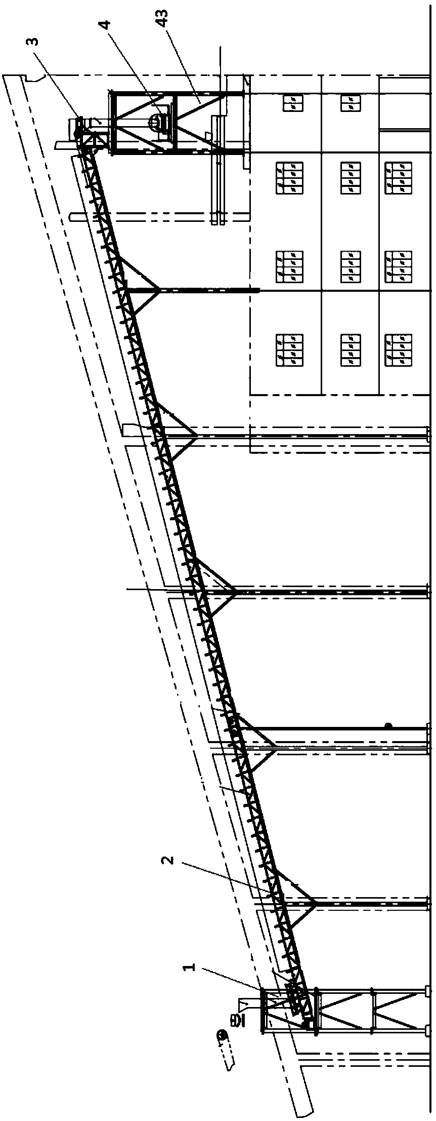
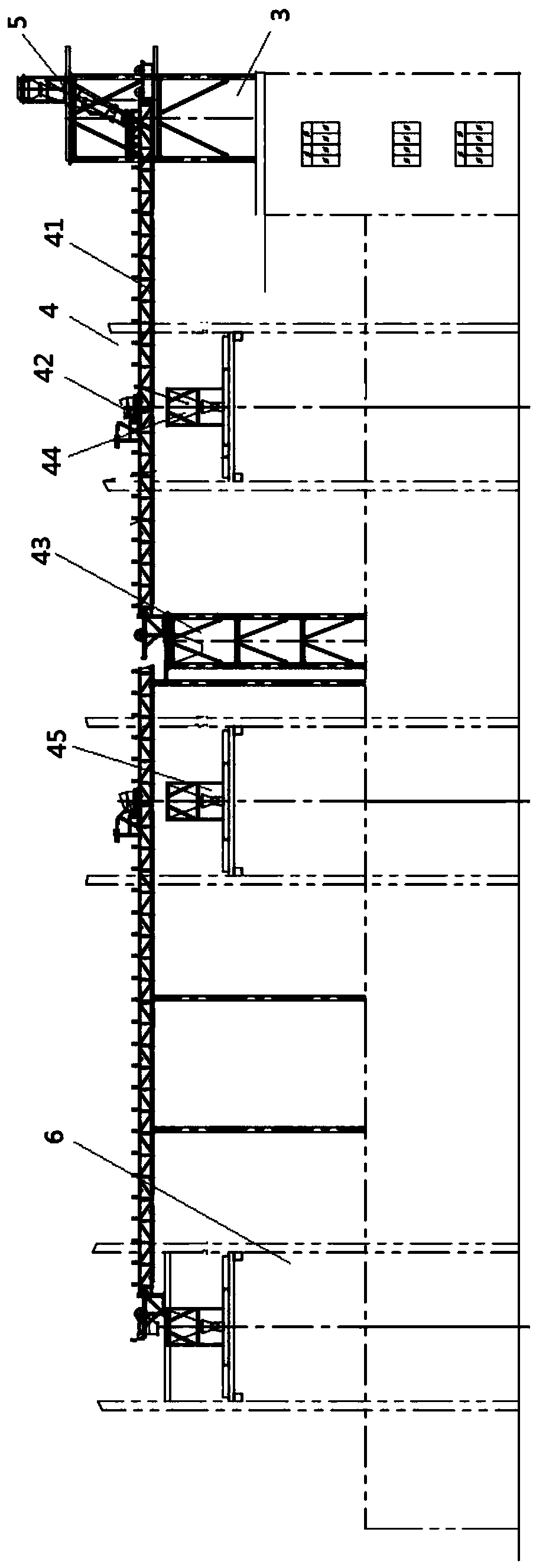
[0015] see figure 1 and figure 2 , this specific embodiment discloses a dry slime incineration system directly into the furnace, including a hopper 1, a conveyor belt 2, a coal conveying system 3, a mud conveying system 4, a coal slime conversion platform 5 and a boiler 6, the coal conveying system 3 and the coal conveying system The mud system 4 is respectively connected to the coal slime conversion platform 5 through a three-way connection. During use, the coal conveying system 3 and the mud conveying system 4 are respectively connected by rotating the three-way to convey the mud cake or coal cake....


PUM


Abstract

The invention discloses an incineration system for drying mud directly into a furnace. Its innovative point is that it includes a hopper, a conveyor belt, a coal conveying system, a mud conveying system, a coal slime conversion platform and a boiler. The coal conveying system and the mud conveying system are respectively It is connected with the coal slime conversion platform through a tee, the hopper and the coal slime conversion platform are respectively located at both ends of the conveyor belt, the output end of the coal conveying system is located at the furnace bottom of the boiler, and the output end of the mud conveying system is located at the bottom of the boiler position of the furnace. The invention has the advantages that the mud cake spreads evenly in the furnace, and after the mud cake is evenly mixed with air and coal, it can ensure sufficient combustion without affecting the fluidization of the bed material in the lower part of the furnace. By transporting the coal cake to the bottom of the furnace, it can effectively solve the phenomenon that the mud cake is easy to stick, bridge, and block in the coal bunker and the coal feeder track after being blended into the fuel, resulting in frequent coal breakage, reducing the need for boiler operation. The disturbance of the environment, and can greatly improve the incineration efficiency.

Description

technical field [0001] The invention relates to sludge treatment equipment, in particular to an incineration system in which dried sludge is directly fed into a furnace. Background technique [0002] Sludge incineration treatment is the most commonly used method for chemical plant or municipal domestic sludge treatment, but industrial sludge or domestic sludge usually contains carbon cakes. In the prior art, carbon cakes and sludge cakes are Incinerate together. When incinerated in this way, after the mud cake is blended into the fuel, it is easy to stick, bridge, and block in the coal bunker and the coal feeder track, resulting in frequent coal breaks. The mud cake is blended when the coal-fired slime enters the dense-phase area of ​​the furnace through the coal feeder. Since the height between the coal drop port and the air distribution plate is 1 meter, the mud cake with larger particles sinks rapidly into the lower part of the dense-phase area after entering the furnace,...

Claims


Application Information

Patent Timeline
IPC IPC(8): F23G7/00
CPCF23G7/001F23G2203/8016F23G2204/101F23G2205/122
Inventor 唐鹏
Owner 南通新源环保有限公司
Learn More