
Overlapped spiral type sludge dewatering machine

A sludge dewatering machine and sludge dehydration technology, which is applied in water/sludge/sewage treatment, sludge treatment, dehydration/drying/thickened sludge treatment, etc., can solve low production efficiency, unfavorable sludge incineration treatment, Difficult to deal with centralized treatment of filtrate and sludge

Pending Publication Date: 2018-04-20
天津远新环保科技有限公司
View PDF9 Cites 3 Cited by
  • Summary
  • Abstract
  • Description
  • Claims
  • Application Information

AI Technical Summary

Problems solved by technology

[0002] Sewage treatment plants will produce sludge during the process of sewage treatment. Since there is still a large amount of water in the sludge, if it is not treated or treated improperly and discharged, it is not conducive to the incineration of sludge, and will give Water and air cause secondary pollution
The existing screw stacking sludge dewatering machines generally only have one set of screw stacking dewatering devices, and the production efficiency is relatively low. If a large amount of sludge needs to be processed, multiple sludge dewatering machines must be purchased, which not only costs high, but also occupies an area of Relatively large, and it is difficult to achieve centralized treatment of filtrate and sludge

Method used


Image

  • Overlapped spiral type sludge dewatering machine
  • Overlapped spiral type sludge dewatering machine

Examples


Embodiment Construction

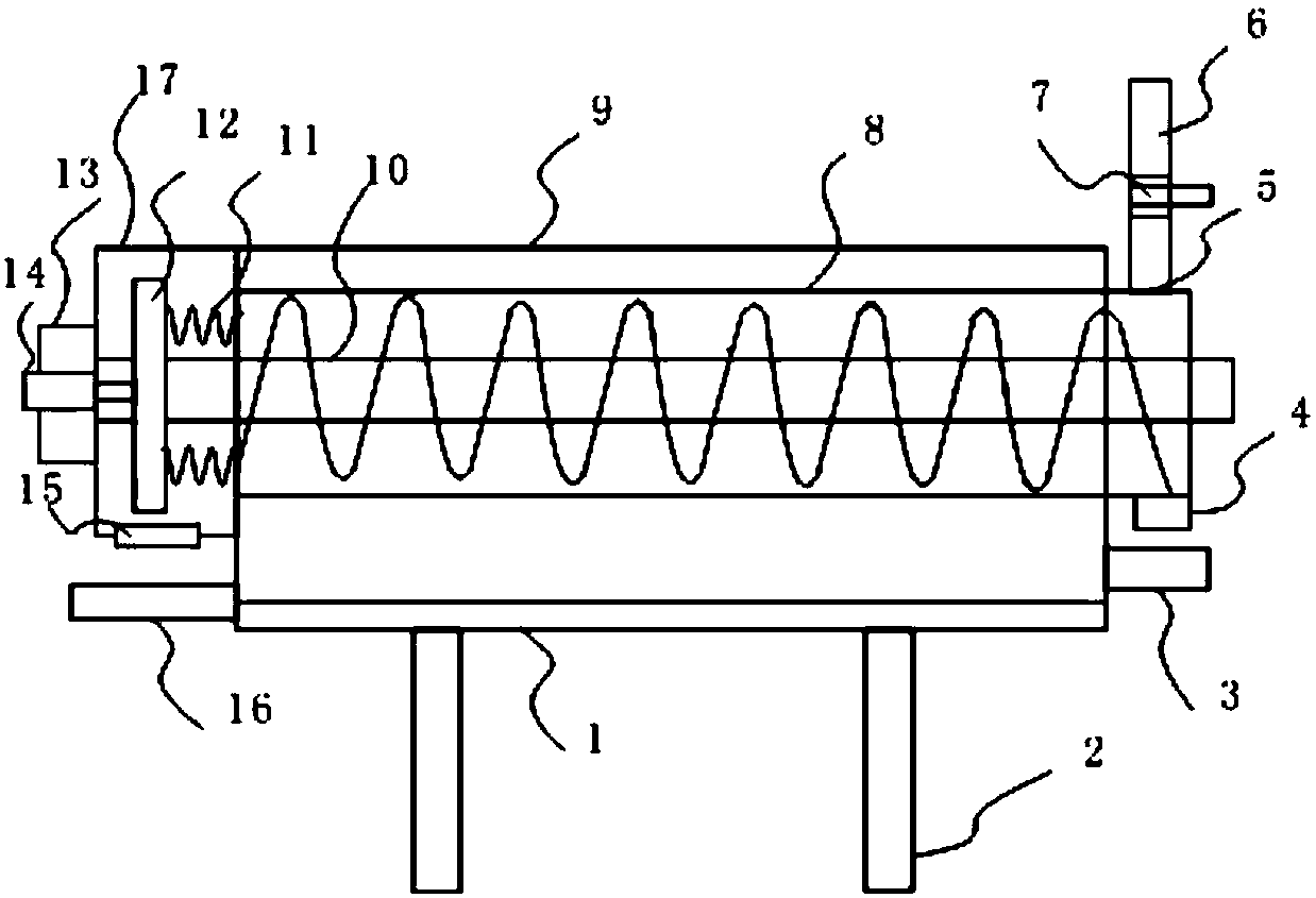
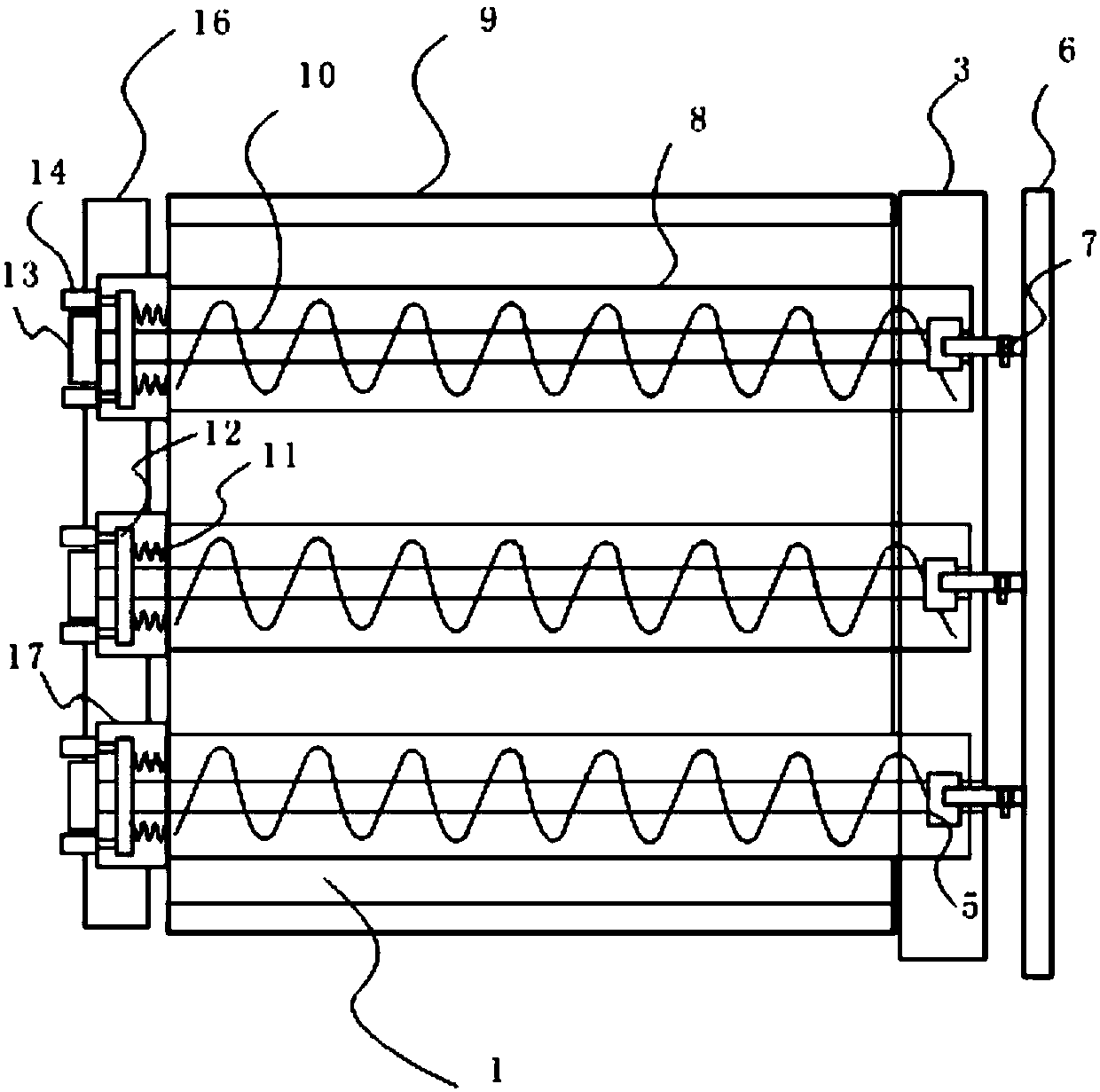
[0017] A screw-stacked sludge dewatering machine, which includes a frame 2 and a screw-stacked sludge dewatering device. The frame includes a bottom plate 1 and baffles 9 hinged to the bottom plate on both sides. The screw-stacked sludge dewatering device is A plurality of them are arranged side by side on the bottom plate, and each stacked screw type sludge dewatering device includes a rotating shaft 10 arranged along the bottom plate and driven by a motor 13, and a screw stacking mechanism 8 sleeved on the shaft to rotate with the shaft, and the downstream end of the stacking screw mechanism There is a feed inlet 5 at the top, and a filtrate outlet 4 at the bottom. Filtrate tanks 3 connected to each other and arranged obliquely are fixedly installed below the filtrate outlets of multiple screw-stacking sludge dewatering devices. The upstream end of the screw-stacking mechanism is provided with A mud discharge chamber 17 connected with the stacking screw mechanism, the mud dis...


PUM


Abstract

The invention relates to the field of sludge treatment equipment and in particular relates to an overlapped spiral type sludge dewatering machine. The overlapped spiral type sludge dewatering machineis characterized by comprising a rack and overlapped spiral type sludge dewatering devices, wherein the rack comprises a bottom plate and a baffle plate and two sides of the baffle plate are hinged with the bottom plate; a plurality of overlapped spiral type sludge dewatering devices are arranged on the bottom plate in parallel; each overlapped spiral type sludge dewatering device comprises a rotary shaft which is arranged along the bottom plate and is driven by a motor, and an overlapped spiral mechanism which sleeves the rotary shaft and rotates along the rotary shaft; a feeding opening is formed above a downstream end of each overlapped spiral mechanism and a filtrate outlet is formed below the downstream end of each overlapped spiral mechanism; filtrate grooves, which are communicatedwith one another and are obliquely arranged, are fixedly mounted below the filtrate outlets of the plurality of overlapped spiral type sludge dewatering devices; a mud discharging cavity communicatedwith each overlapped spiral mechanism is formed in an upstream end of each overlapped spiral mechanism; each mud discharging cavity is provided with a mud discharging opening; a belt conveyor is mounted below the plurality of mud discharging openings. The device provided by the invention has the advantages of low cost, small land occupation and high efficiency and can realize centralized treatmentof sludge and filtrate.

Description

technical field [0001] The invention relates to the field of sludge treatment equipment, in particular to a screw stacking sludge dehydrator. Background technique [0002] Sewage treatment plants will produce sludge during the process of sewage treatment. Since there is still a large amount of water in the sludge, if it is not treated or treated improperly and discharged, it is not conducive to the incineration of sludge, and will give Water and air cause secondary pollution. The existing screw stacking sludge dewatering machines generally only have one set of screw stacking dewatering devices, and the production efficiency is relatively low. If a large amount of sludge needs to be processed, multiple sludge dewatering machines must be purchased, which not only costs high, but also occupies an area of It is relatively large, and it is difficult to realize the centralized treatment of filtrate and sludge. Contents of the invention [0003] The technical problem to be solv...

Claims


Application Information

Patent Timeline
Patent Type & Authority Applications(China)
IPC IPC(8): C02F11/12
CPCC02F11/125
Inventor 王学科马竞男穆童谢迎辉芦珊珊刘静伟吴建光张永旺
Owner 天津远新环保科技有限公司
Learn More