
Disorderly feeding device

A positioning device and material channel technology, which is used in transportation and packaging, conveyor objects, conveyors, etc., can solve the problems of lack of positioning device in the transmission channel, reducing feeding efficiency, and workpiece skewing, etc., to ensure transmission efficiency, increase Feeding efficiency and the effect of preventing stacking

Active Publication Date: 2021-06-04
WUHAN HEATKING MACHINE ELECTRICAL EQUIP
View PDF0 Cites 0 Cited by
  • Summary
  • Abstract
  • Description
  • Claims
  • Application Information

AI Technical Summary

Problems solved by technology

[0002] The disorderly feeding device is used to realize the transmission of disordered workpieces in the silo. The lifting device of the traditional disordered feeding device uses a one-time lifting method to transport the workpieces to the designated position. This structure is prone to workpiece stacking during transmission. Phenomenon, especially when transferring workpieces with inconsistent sizes at both ends, such as riveting pins, the stacking phenomenon is more obvious
In addition, the transmission channel of the traditional disorderly feeding device is a single transmission channel, which can only transport one row of workpieces at a time, which is inefficient
In addition, there is no positioning device at the end of the transmission path, and the workpiece is prone to skewing, so that the phenomenon of material dropping or grasping failure occurs during the process of grabbing the workpiece by the manipulator, which further reduces the feeding efficiency

Method used


Image

  • Disorderly feeding device
  • Disorderly feeding device
  • Disorderly feeding device

Examples


Embodiment Construction

[0030] In order to make the object, technical solution and advantages of the present invention clearer, the present invention will be further described in detail below in conjunction with the accompanying drawings and embodiments. The specific embodiments described here are only used to explain the present invention, not to limit the present invention. In addition, the technical features involved in the various embodiments of the present invention described below can be combined with each other as long as they do not constitute a conflict with each other.

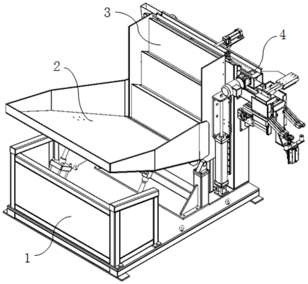
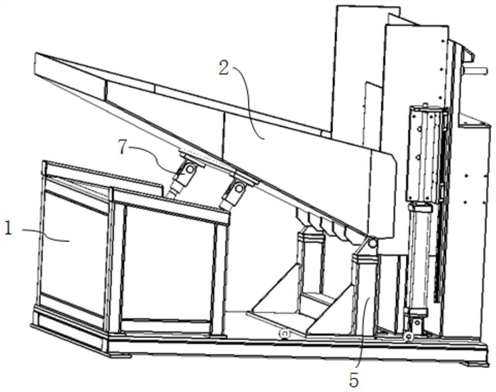
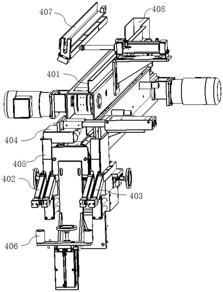
[0031] Such as figure 1 As shown, the disorderly feeding machine using the material distribution positioning device of the present invention includes a support 1 , a material bin 2 , a feeding mechanism 3 and a material distribution positioning device 4 . Bracket 1, feed bin 2, and feeding mechanism 3 are the main components of the ladder feeding device, such as Figure 10 As shown, the step feeding device is connected wi...


PUM


Abstract

The invention relates to the technical field of disorderly feeding, in particular to a disorderly feeding device. It includes a bracket and a silo fixed on the bracket, and also includes a step feeding device and a material distribution positioning device. mechanism, the material distributing positioning device includes a material distributing mechanism and a material shifting mechanism, the material distributing mechanism includes a first material channel and a second material channel arranged on both sides of the end of the transmission mechanism, and the material distributing mechanism is arranged on the transmission mechanism Above the end, the material shifting mechanism can reciprocate along a direction perpendicular to the conveying mechanism, and distribute adjacent workpieces on the conveying mechanism to the first material path and the second material path during the reciprocating movement. The device can realize material distribution and transmission of workpieces, improve feeding efficiency and prevent stacking.

Description

technical field [0001] The invention relates to the technical field of disorderly feeding, in particular to a disorderly feeding device. Background technique [0002] The disorderly feeding device is used to realize the transmission of disordered workpieces in the silo. The lifting device of the traditional disordered feeding device uses a one-time lifting method to transport the workpieces to the designated position. This structure is prone to workpiece stacking during transmission. Phenomenon, especially when transferring workpieces with inconsistent sizes at both ends, such as riveting pins, the stacking phenomenon is more obvious. In addition, the transmission channel of the traditional disorderly feeding device is a single transmission channel, which can only transport one row of workpieces at a time, which is inefficient. In addition, there is no positioning device at the end of the transmission path, and the workpiece is prone to skewing, so that the phenomenon of ma...

Claims


Application Information

Patent Timeline
Patent Type & Authority Patents(China)
IPC IPC(8): B65G47/14
CPCB65G47/1407B65G2201/02
Inventor 柯尊华
Owner WUHAN HEATKING MACHINE ELECTRICAL EQUIP
Learn More