Node diagnosis device and system
A technology for diagnosing devices and nodes, applied in the network field, can solve problems such as ineffective work, and achieve the effects of simple signaling and low identification complexity
- Summary
- Abstract
- Description
- Claims
- Application Information
AI Technical Summary
Problems solved by technology
Method used
Image
Examples
Embodiment 1
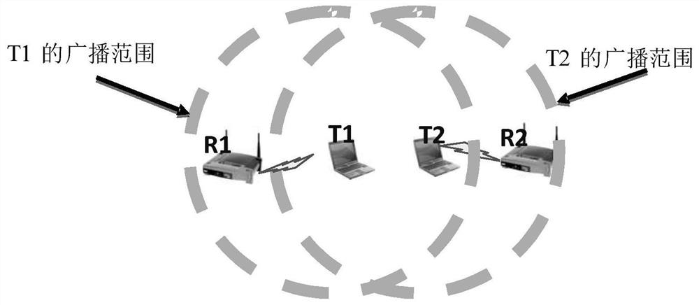
[0054] Embodiment 1 of the present invention provides a node diagnosis method, which is applied to the control node side. Figure 8 is a schematic diagram of a node diagnosis method according to an embodiment of the present invention, such as Figure 8 As shown, the node diagnosis method includes:
[0055] Step 801, receiving notifications related to channel busyness reported by other nodes;
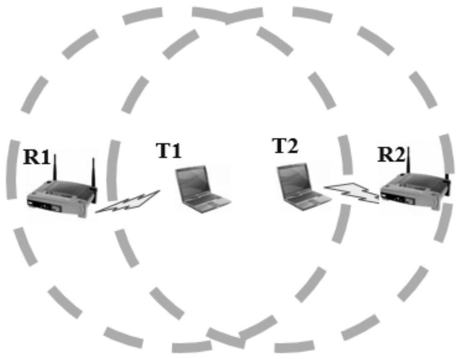
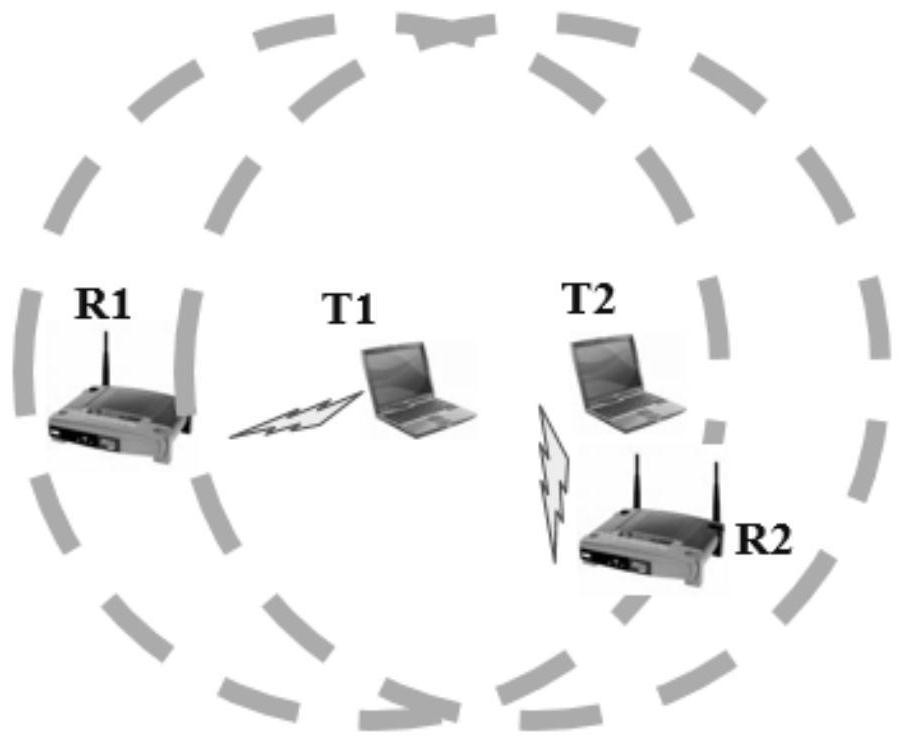
[0056] Step 802, after receiving the first notification related to channel busyness reported by the first node and the second notification related to channel busyness reported by the second node, and the first node and the second node are in different basic services When set (BasicService Set, BSS), send a control signal to the first node and the second node, so that the first node and the second node send test data packets respectively within the first time according to the control signal;
[0057] Step 803, receiving one or more first parameters related to the success rate of data tr...
Embodiment 2
[0084] Embodiment 2 of the present invention provides a node diagnosis method, the method is applied to the first node and / or the second node, wherein the first node and / or the second node is the network without the control described in Embodiment 1 Other ordinary nodes outside the node. Since the processes of the first node and the second node are the same or similar, the first node will be used as an example for description below.
[0085] Figure 9 is a schematic diagram of a node diagnosis method according to an embodiment of the present invention, such as Figure 9 As shown, the node diagnosis method includes:
[0086] Step 901, generating a first notification related to channel busyness;
[0087] Step 902, reporting the first notification to the control node;
[0088] Step 903, receiving the control signal issued by the control node; where the control signal is determined by the control node and also receives a second notification related to channel busyness reported...
Embodiment 3
[0106] Embodiment 3 of the present invention provides a node diagnosis method, which is further described from the perspective of the network, and the same content as Embodiments 1 and 2 will not be repeated.
[0107] Figure 10 is a schematic diagram of a node diagnosis method according to an embodiment of the present invention, such as Figure 10 As shown, the node diagnosis method includes:
[0108] Step 1001, a node in the network generates a notification related to channel busyness and reports the notification to the control node;
[0109] Wherein, the specific implementation manner of the node (for example, the first node or the second node) generating the notification and reporting it to the control node can refer to steps 901-902 in Embodiment 2, which will not be repeated here.
[0110] Step 1002, the control node receives a notification reported by one or more nodes;
[0111] Step 1003, the control node judges whether the first notification related to channel busy...
PUM
 Abstract
Description
Claims
Application Information
 - Generate Ideas
- Intellectual Property
- Life Sciences
- Materials
- Tech Scout
- Unparalleled Data Quality
- Higher Quality Content
- 60% Fewer Hallucinations
Browse by: Latest US Patents, China's latest patents, Technical Efficacy Thesaurus, Application Domain, Technology Topic, Popular Technical Reports.
© 2025 PatSnap. All rights reserved.Legal|Privacy policy|Modern Slavery Act Transparency Statement|Sitemap|About US| Contact US: help@patsnap.com


