Remote control lighting system based on energy consumption management

A lighting system and remote control technology, applied in general control systems, control/adjustment systems, program control, etc., can solve the problems of troublesome wiring, many lighting equipment, waste of resources, etc., to improve home comfort, reduce layout and wiring, Energy saving effect

Pending Publication Date: 2018-04-17
GUANGZHOU XINGCHEN HEAT ENERGY CO LTD
View PDF3 Cites 4 Cited by
  • Summary
  • Abstract
  • Description
  • Claims
  • Application Information

AI Technical Summary

Problems solved by technology

[0004] The lamps and lights in the room will have different effects on people's mood. The existing lighting equipment in the home cannot adjust the lights adaptively according to the changes of the external environment.
[0005] When people leave the room, living room, kitchen or bathroom for a long time, they often forget to turn off the lights, resulting in a waste of resources;
[0006] A variety of lighting devices are often installed in existing homes, but the power consumption of each lighting device is different, and it is impossible to detect the power consumption and power consumption of each device in real time;
[0007] Each lighting device in the existing home is equipped with an independent switch, which is controlled independently and cannot be regulated uniformly;
[0008] The traditional intelligent lighting system is generally set up in a wired way. There are many lighting equipment and household appliances in the existing home, which makes wiring troublesome.

Method used


Image

  • Remote control lighting system based on energy consumption management
  • Remote control lighting system based on energy consumption management
  • Remote control lighting system based on energy consumption management

Examples


Embodiment 1

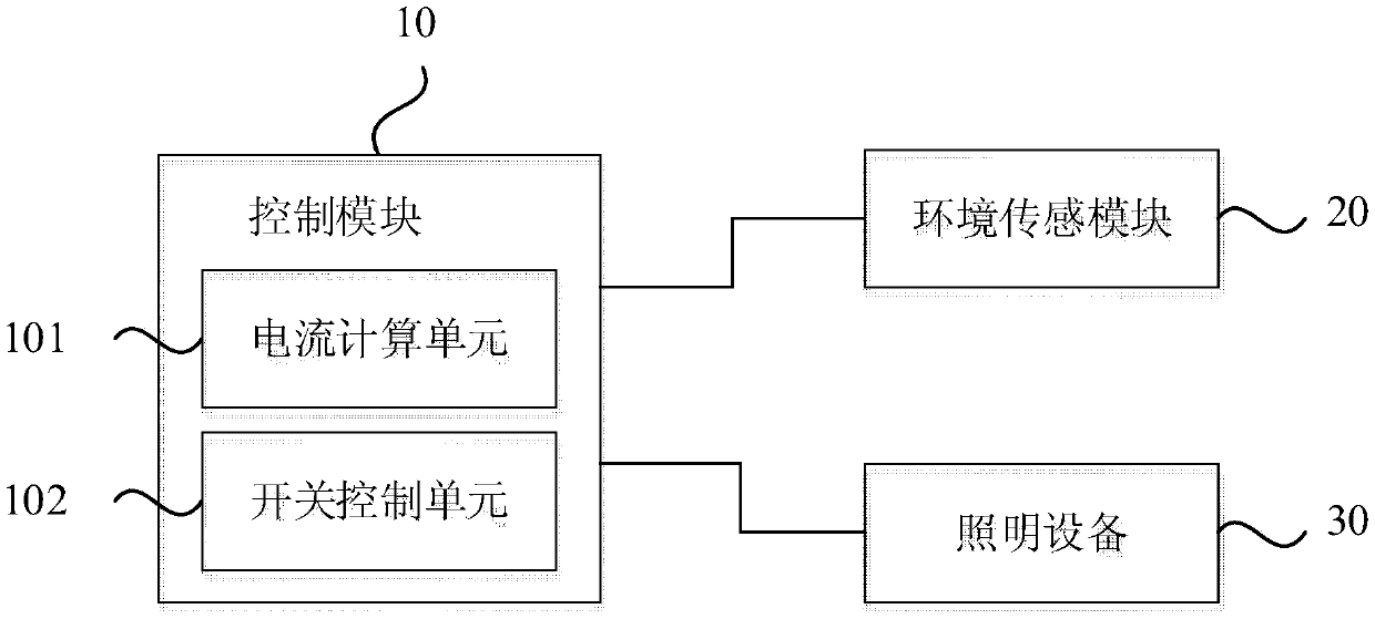
[0034] figure 1 It is a schematic structural diagram of a remote control lighting system based on energy consumption management provided in the first embodiment of the present invention, such as figure 1 As shown, the lighting system includes: a control module 10, an environment sensing module 20, and a lighting device 30.

[0035] The control module 10 includes a current calculation unit 101 and a switch control unit 102, and a current calculation unit 101 and a switch control unit 102 are respectively provided on the path of each lighting device 30. The current calculation unit 101 is used to measure the current size of the corresponding lighting device 30 during operation; the switch control unit 102 is used to control the turning on and off of the corresponding lighting device 30;

[0036] The environment sensing module 20, connected to the control module 10, is used to sense environmental information and send the environmental information to the control module 10;

[0037] The c...

Embodiment 2

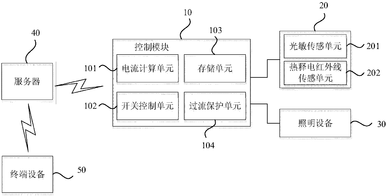
[0047] image 3 It is a schematic structural diagram of a remote control lighting system based on energy consumption management provided in the second embodiment of the present invention, such as image 3 As shown, on the basis of the foregoing embodiment, the control module 10 in the lighting system provided in this embodiment further includes a storage unit 103 and an overcurrent protection unit 104.

[0048] Among them, the storage unit 103 is built into the control module 10, and is used to store the control information of the lighting device 30 with an independent address, so that damage to the storage unit corresponding to any lighting device 30 will not affect the performance of other lighting devices 30 in the lighting system. normal work. The overcurrent protection unit 104 is connected to each lighting device 30 to prevent permanent damage to the lighting device 30 caused by excessive starting current or thermal shock. When the lighting device 30 is turned on, a relativ...

Embodiment 3

[0058] Figure 4 The third embodiment of the present invention provides a schematic structural diagram of a remote control lighting system based on energy consumption management. Such as Figure 4 As shown, the environment sensing module 20 is embedded in the control module 10, and a multi-path module 60 can be provided to connect multiple paths to the lighting device 30. At this time, one control module 10 can set multiple paths to connect to multiple different lighting devices 30, which can be: lighting device 1, lighting device 2, lighting device 3... lighting device N, preferably, one control is set for one room In the module 10, a module 10 is embedded with a variety of environmental sensing modules 20, and controls different lighting devices 30 through multiple external channels such as a 3-way module and a 5-way module. Specifically, if a 3-way module is connected externally, the control module 10 can connect to the lighting device 30 on three different paths at most. ...


PUM


Abstract

The invention discloses a remote control lighting system based on energy consumption management, which comprises a control module, an environment sensing module and lighting equipment, wherein the control module comprises a current calculation unit and a switch control unit, and the current calculation unit is used to measure the current magnitude when corresponding lighting equipment works; the switch control unit is used for controlling on and off of the corresponding lighting equipment; the environment sensing module is connected with the control module for sensing the environment information and transmitting the environment information to the control module; the control module is also used to adjust the brightness of the lighting equipment according to the received environment information; and the lighting equipment is connected with the control module for receiving a control instruction of the control module and completing light adjustment. Placement and routing in the home are reduced, automatic control, unified control and remote control on the lighting equipment in the smart home are realized, and while the home comfort of a user is improved, the energy consumption is saved, and the management is facilitated.

Description

Technical field [0001] The embodiment of the present invention relates to smart home technology, in particular to a remote control lighting system based on energy consumption management. Background technique [0002] At present, with the continuous improvement of people's living standards, people have higher and higher requirements for the living environment. Whether in terms of life experience or environmental protection and energy saving, higher requirements are put forward on the existing home lighting equipment system. [0003] At present, the existing home lighting equipment mainly has the following shortcomings: [0004] The lights and lights in the room will have different effects on people's mood, and the existing home lighting equipment cannot adjust the lights adaptively according to the changes of the external environment. [0005] When people leave the room, living room, kitchen or bathroom for a long time, they often forget to turn off the lights, causing a waste of reso...

Claims


Application Information

Patent Timeline
Patent Type & Authority Applications(China)
IPC IPC(8): G05B15/02G05B19/418
CPCG05B15/02G05B19/418G05B2219/2642
Inventor 许剑武黄明才
Owner GUANGZHOU XINGCHEN HEAT ENERGY CO LTD
Why Eureka
Try Eureka