Chute corbel pillar masonry structure of dry quenching furnace

A technology of masonry structure and dry quenching furnace, which is applied in the field of refractory materials, can solve problems such as the inability to meet the production needs of dry quenching furnaces, and achieve the possible effect of reducing the possibility of blasting

Pending Publication Date: 2018-04-17
MAANSHAN IRON & STEEL CO LTD
View PDF3 Cites 0 Cited by
  • Summary
  • Abstract
  • Description
  • Claims
  • Application Information

AI Technical Summary

Problems solved by technology

Although the above-mentioned several chute corbels have been improved and have achieved certain effects, they still cannot meet the production needs of the CDQ furnace's service life.

Method used


Image

  • Chute corbel pillar masonry structure of dry quenching furnace
  • Chute corbel pillar masonry structure of dry quenching furnace
  • Chute corbel pillar masonry structure of dry quenching furnace

Examples


Embodiment Construction

[0026] First of all, it should be noted that the characteristics and advantages of the corbel pillar masonry structure of the CDQ furnace chute of the present invention will be specifically described below by way of example, but all descriptions are only for illustration, and should not be It is understood to form no limitation on the invention. In addition, any single technical feature described or implied in each embodiment mentioned herein, or any single technical feature shown or implied in each drawing, can still be described in these technical features (or their equivalents) ) to continue any combination or deletion, so as to obtain more other embodiments of the present invention that may not be directly mentioned herein.

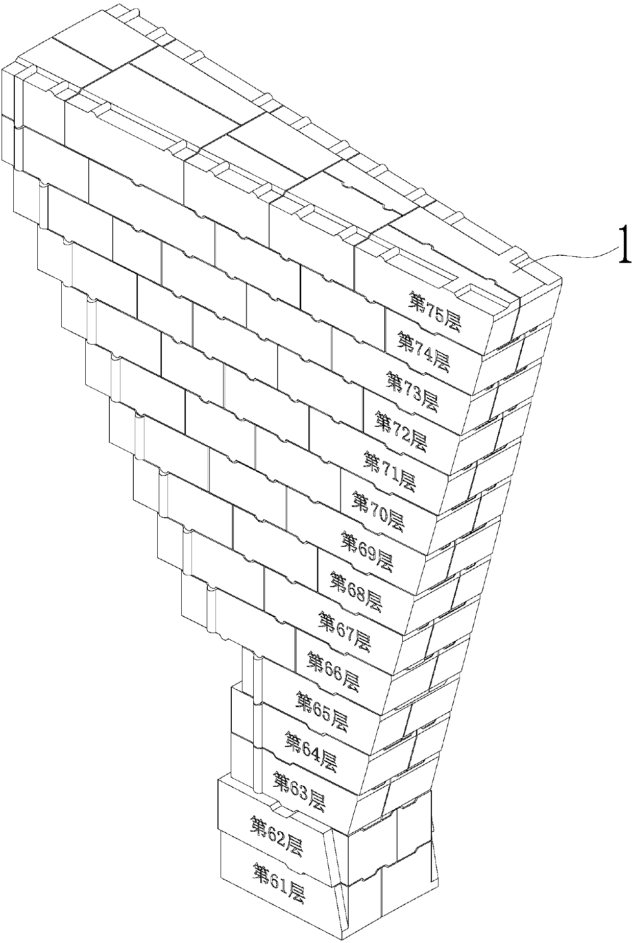
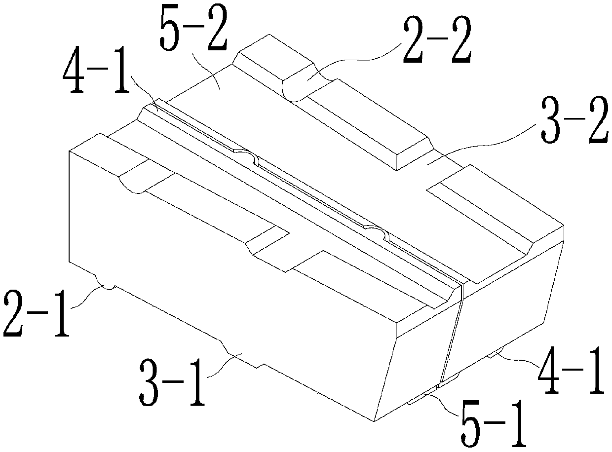
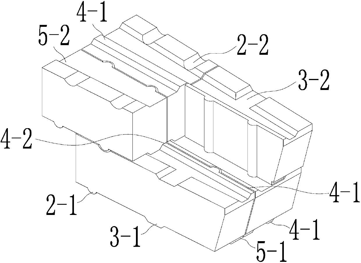
[0027] Figure 1 to Figure 9 As shown, the following example will be used to illustrate the masonry structure of the CDQ furnace chute corbels of the present invention through this given embodiment.

[0028] Taking our company's 140-ton dry quenchin...


PUM


Abstract

The invention discloses a chute corbel pillar masonry structure of a dry quenching furnace. The structure is characterized by comprising a plurality of layers of double-row corbel pillar bricks whichare alternately arranged in the height direction, wherein adjacent corbel pillar bricks of each layer of double-row corbel pillar bricks in the length direction extend along an axial line and are in plane fit, and the adjacent corbel pillar bricks in the width direction are arranged in parallel and are in buckled connection through a brick ditch and a brick tongue of a B type brick; the adjacent head-on corbel pillar bricks of the upper layer and the lower layer are in buckled connection by a brick ditch and a brick tongue of a D type brick, a brick ditch and a brick tongue of an H type brick,a brick ditch and a brick tongue of an S type brick and / or a brick ditch and a brick tongue of a B type brick, and other adjacent corbel pillar bricks of the upper layer and the lower layer are in buckled connection by the brick ditches and the brick tongues of the B type bricks, the brick ditches and the brick tongues of the H type bricks and the brick ditches and the brick tongues of the S typebricks. The engagement between the bricks of the whole corbel pillar is sufficient and reasonable; the possibility of crackling of the head-on bricks of the corbel pillar is reduced by mutual engagement between the upper layer and the lower layer.

Description

technical field [0001] The invention belongs to the technical field of refractory materials, and in particular relates to a masonry structure of a chute corbel pillar of a CDQ furnace. Background technique [0002] CDQ furnace (abbreviation: CDQ furnace) is an important device of CDQ system. The upper part of the CDQ furnace is a pre-storage room and an annular air duct surrounding the pre-storage room and communicating with the pre-storage room. The lower part is a cooling room. The structure connecting the previous and the next, its components mainly include corbels, which are the key parts, and the inclined corbels of the double brick structure, after running for a period of time, there will be problems of brick displacement and serious cracking of the facing brick joints. The corbel pillars support the weight of the circular air duct of the CDQ furnace of about 200 tons. If the cracking of the pillars is not solved in time, the long-term friction between the coke and th...

Claims


Application Information

Patent Timeline
IPC IPC(8): C10B39/02C10B29/02C10B29/08
CPCC10B29/02C10B29/08C10B39/02
Inventor 钱虎林王春洪丁君涛储叶君夏鹏飞刘府根张松林王飞佘世云
Owner MAANSHAN IRON & STEEL CO LTD
Why Eureka
Try Eureka