
Oiling pipe placing rack for oiling machine

A technology for placing racks and refueling machines, which is applied in distribution devices, special distribution devices, liquid distribution, transportation or transfer devices, etc. It can solve problems such as failure to meet refueling requirements, reduced service life of oil pipes, and inconvenient actions for operators, so as to avoid Tilting, prolonging the service life, improving the effect of using stability

Inactive Publication Date: 2018-04-17
张金立
View PDF0 Cites 0 Cited by
  • Summary
  • Abstract
  • Description
  • Claims
  • Application Information

AI Technical Summary

Problems solved by technology

[0003] 1. The refueling pipe is generally hung on the outer wall of the fuel dispenser, and the length of the refueling pipe is long, directly in contact with the ground. During long-term use, the service life of the fuel pipe is reduced and cannot meet the refueling requirements
[0004] 2. The length of the fuel pipe is long and it is placed on the ground, which brings inconvenience to the operator's actions and cannot meet people's needs.

Method used


Image

  • Oiling pipe placing rack for oiling machine
  • Oiling pipe placing rack for oiling machine

Examples


Embodiment Construction

[0017] The following will clearly and completely describe the technical solutions in the embodiments of the present invention with reference to the accompanying drawings in the embodiments of the present invention. Obviously, the described embodiments are only some, not all, embodiments of the present invention. Based on the embodiments of the present invention, all other embodiments obtained by persons of ordinary skill in the art without making creative efforts belong to the protection scope of the present invention.

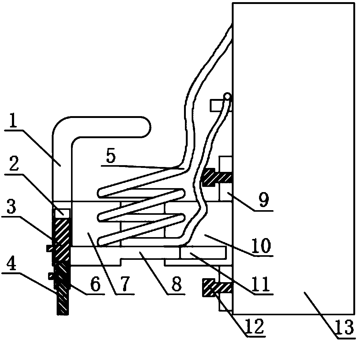
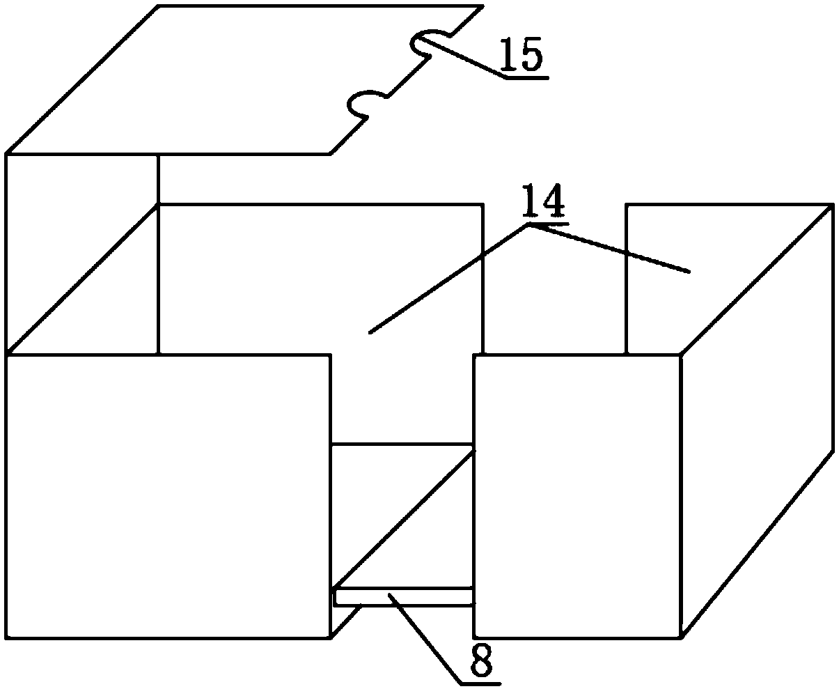
[0018] see Figure 1-2 , the present invention provides a technical solution: a refueling pipe placement rack for a fuel dispenser, including a movable placement rack 7, a fixed placement rack 10, and a fuel dispenser 13, the outer wall of the fuel dispenser 13 is threadedly fixed by thick diameter bolts 12. Mounting plate 9, four thick-diameter bolts 12 are provided in total, and four thick-diameter bolts 12 are evenly distributed at the four corners of the m...


PUM


Abstract

The invention discloses a filling pipe placement frame for a fuel dispenser, which comprises a movable mounting frame, a fixed mounting frame and a fuel dispenser. There are four, and the four thick-diameter bolts are evenly distributed at the four corners of the installation plate. A fixed placement frame is fixedly installed in the center of the installation plate, and a slot is opened inside the side of the fixed placement frame near the lower end. , one side of the slot is movably inserted with a flashboard, one side of the flashboard is fixedly connected with a movable shelf, and the upper wall of the movable shelf away from the side of the fuel dispenser is welded with a protective cover; the present invention The fueling pipe rack is a telescopic structure. When in use, the flexible connection between the insert plate and the slot is used to increase the space for the fueling pipe. It not only provides a place for the fueling pipe, but also effectively prevents the fueling pipe from contacting the ground. Effective protection in case of damage.

Description

technical field [0001] The invention relates to the technical field of fueling machine auxiliary equipment, in particular to a fueling pipe placement frame for a fueling machine. Background technique [0002] Fuel dispensers are generally installed in gas stations to provide refueling conditions for cars and other vehicles. Refueling pipes play a key role as the necessary equipment for the oil output of fuel dispensers. However, there are some deficiencies in the existing fuel dispenser pipes during use. place. [0003] 1. The refueling pipe is generally hung on the outer wall of the fuel dispenser, and the length of the refueling pipe is long, directly in contact with the ground. During long-term use, the service life of the fuel pipe is reduced and cannot meet the refueling requirements. [0004] 2, the longer length of the oil filling pipe is placed on the ground to bring inconvenience to the operator's actions and cannot meet people's needs. Contents of the invention ...

Claims


Application Information

Patent Timeline
Patent Type & Authority Applications(China)
IPC IPC(8): B67D7/40
CPCB67D7/40
Inventor 张金立
Owner 张金立
Learn More