
Printing platform clamping device for automation line PCB

A PCB circuit board and printing platform technology, applied in printing, typewriters, etc., can solve problems such as low production efficiency, large demand for circuit board production sites, and low efficiency

Pending Publication Date: 2018-04-17
선전진신테크놀로지컴퍼니리미티드
View PDF6 Cites 4 Cited by
  • Summary
  • Abstract
  • Description
  • Claims
  • Application Information

AI Technical Summary

Problems solved by technology

[0002] In the production process of character printing on circuit boards, the PCB board must be positioned before printing can be carried out, and the size of PCB boards of different material numbers is different. Currently, the character printing process of printed circuit boards is usually completed by a special character printing workshop. However, the pick-and-place and positioning of the sheets on the printing table are mostly manual single-machine operations, and the production efficiency is low. Moreover, the character printing production mode that is separated from the upstream and downstream process equipment is inefficient, which makes the production site of the entire circuit board more demanding. , higher labor costs

Method used


Image

  • Printing platform clamping device for automation line PCB
  • Printing platform clamping device for automation line PCB

Examples


Embodiment Construction

[0013] The following will clearly and completely describe the technical solutions in the embodiments of the present invention with reference to the accompanying drawings in the embodiments of the present invention. Obviously, the described embodiments are only some, not all, embodiments of the present invention. Based on the embodiments of the present invention, all other embodiments obtained by persons of ordinary skill in the art without making creative efforts belong to the protection scope of the present invention.

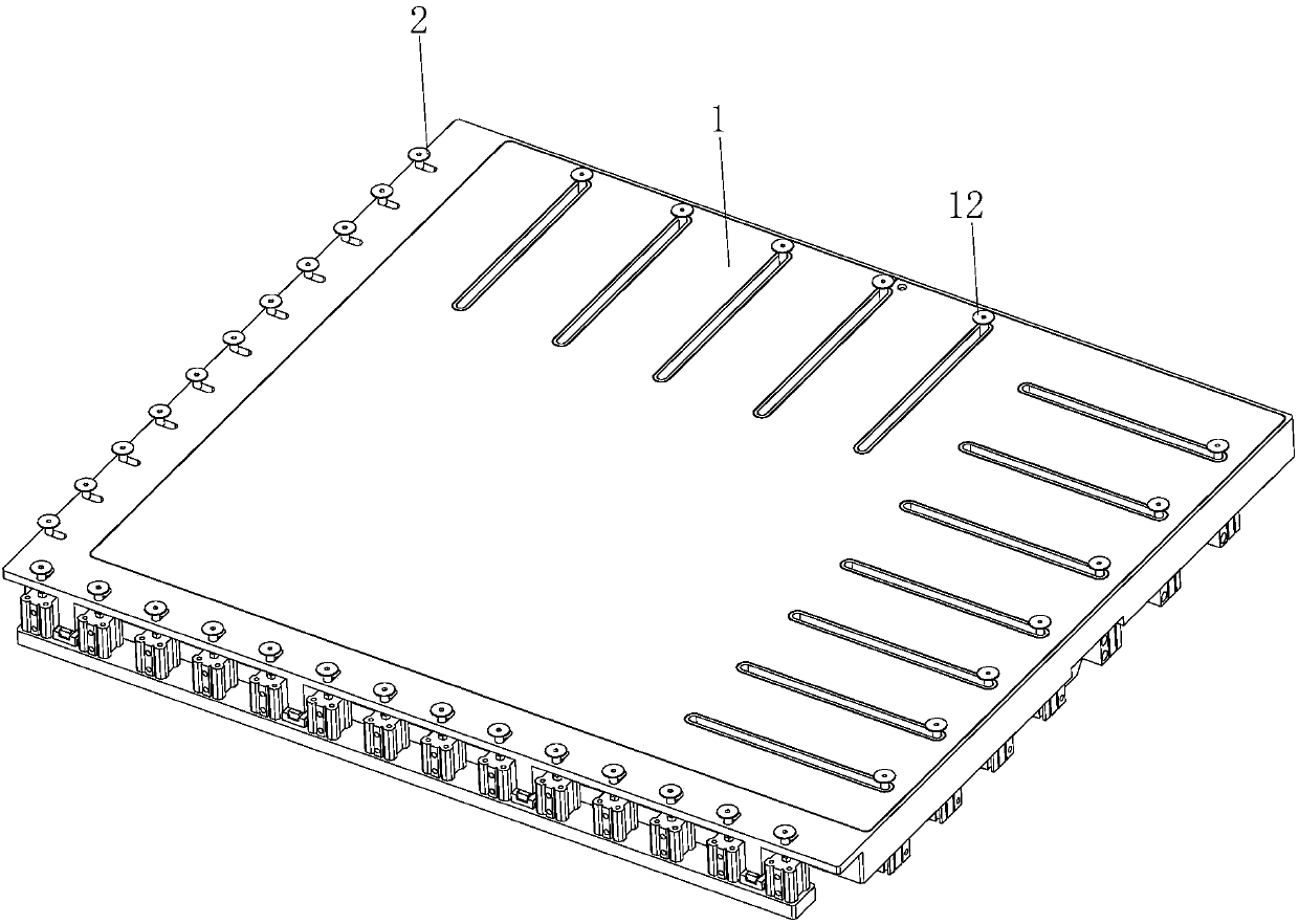
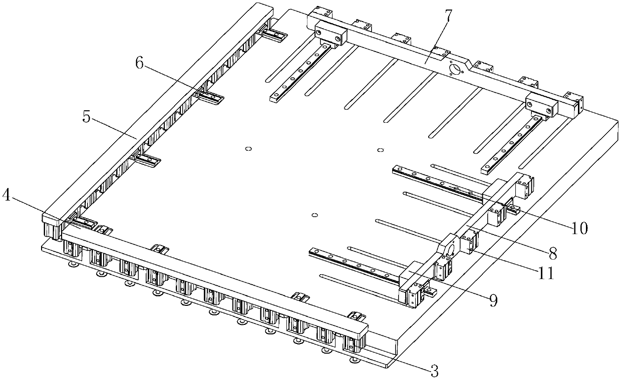
[0014] see Figure 1-2 , a clamping device for an automatic line PCB circuit board printing platform, including a printing table top 1, a guide rail slider pair A6 and a guide rail slider pair B10 are respectively installed on the sides adjacent to the bottom of the printing table top 1, and the guide rail slider pair A6 The X-direction installation bar 5 and the Y-direction installation bar 4 are movable respectively, and a certain number of cylinders A3 are ...


PUM


Abstract

The invention discloses a printing platform clamping device for an automation line PCB. The printing platform clamping device comprises a printing platform surface, wherein guide rail sliding block pairs A and guide rail sliding block pairs B are installed at the adjacent side edges of the printing platform surface separately, the guide rail sliding block pairs A are movably clamped with mountingbars which are loaded with a certain amount of air cylinders A, the guide rail sliding block pairs B are movably clamped with mounting bars which are loaded with a certain amount of air cylinders B, and a corresponding amount of press plate chucks A and press plate chucks B are installed at the output ends of the air cylinders A and the output ends of the air cylinders B respectively. When the printing platform clamping device for the automation line PCB works, a short stroke fixture assembly and a long stroke fixture assembly move to the edges, close to the four sides of the PCB, of the loaded press plate chucks of the assemblies along the respective guide rail sliding block pairs according to routes set by a program, then under the action of the air cylinders A and the air cylinders B, all the press plate chucks A and the press plate chucks B on the four sides descend, thus chuck cap edges compress the periphery of the PCB, and thus the PCB cannot be shifted.

Description

technical field [0001] The invention relates to the technical field of PCB processing equipment, in particular to an automatic line PCB circuit board printing platform clamping device. Background technique [0002] In the production process of character printing on circuit boards, the PCB board must be positioned before printing can be carried out, and the size of PCB boards of different material numbers is different. Currently, the character printing process of printed circuit boards is usually completed by a special character printing workshop. However, the pick-and-place and positioning of the sheets on the printing table are mostly manual single-machine operations, and the production efficiency is low. Moreover, the character printing production mode that is separated from the upstream and downstream process equipment is inefficient, which makes the production site of the entire circuit board more demanding. , higher labor costs. However, the just-emerged printed circui...

Claims


Application Information

Patent Timeline
IPC IPC(8): B41J3/407B41J2/01
CPCB41J2/01B41J3/407
Inventor 徐进刘玲宁海旭
Owner 선전진신테크놀로지컴퍼니리미티드
Learn More