Steerable micro drilling and milling device used for workpiece inner and outer cavity processing

A workpiece and micro-drilling technology, which is applied in the direction of drive devices, metal processing equipment, metal processing machinery parts, etc., can solve the problems of low processing accuracy, efficiency and surface quality, unrealistic processing of three-axis machine tools, and low processing efficiency. The effect of reducing the number of workpiece clamping, expanding the range of processing, and improving processing efficiency

Active Publication Date: 2018-04-17
HENAN POLYTECHNIC UNIV
View PDF7 Cites 5 Cited by
  • Summary
  • Abstract
  • Description
  • Claims
  • Application Information

AI Technical Summary

Problems solved by technology

[0002] With the development of society and actual needs, people's requirements for the performance of mechanical appliances are constantly increasing, and the geometric shapes of mechanical parts and finished products are becoming more and more complex. The processing of workpieces with inner and outer cavities has always been a difficult point in the field of mechanical manufacturing and processing. Machining is almost impossible on three-axis machines
In traditional processing and manufacturing, casting, ...

Method used


Image

  • Steerable micro drilling and milling device used for workpiece inner and outer cavity processing
  • Steerable micro drilling and milling device used for workpiece inner and outer cavity processing
  • Steerable micro drilling and milling device used for workpiece inner and outer cavity processing

Examples


Embodiment Construction

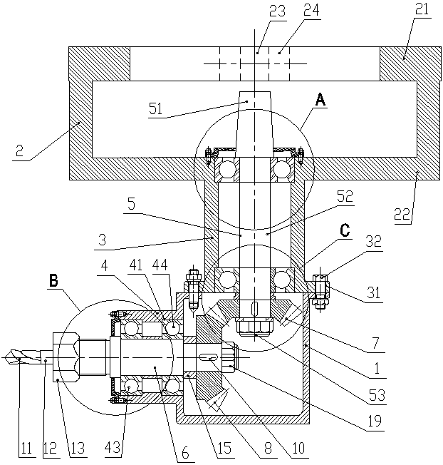
[0036] Such as Figure 1 to Figure 6 Shown in figure 1 The left side of is the left direction of the present invention. The steerable micro-drilling and milling device for machining the inner and outer cavities of workpieces of the present invention includes a connecting frame, a gear box 1, a transmission mechanism and a detachable tool structure,

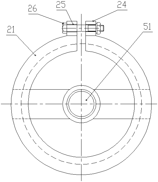
[0037] The connecting frame includes a double-layer ring body 2 at the upper part for connecting with the spindle housing of the vertical milling machine and a cylindrical body 3 at the lower part. The double-layer ring body 2 and the cylindrical body 3 are coaxially fixedly connected, and the cylindrical body 3 The lower end of the gearbox 1 is detachably and fixedly connected to the top of the gearbox 1;

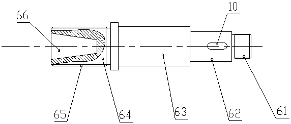
[0038] The left side wall of the gear box 1 is fixedly connected to the output shaft mounting cylinder 4, and the transmission mechanism is arranged in the gear box 1. The transmission mechanism includes a transmission shaft 5, an ...


PUM


Abstract

The invention discloses a steerable micro drilling and milling device used for workpiece inner and outer cavity processing. The steerable micro drilling and milling device comprises a connecting frame, a gearbox, a transmission mechanism and a detachable tool structure, wherein the connecting frame comprises an upper double-layer ring body connected with a vertical type milling machine main shafthousing and a lower cylinder; the transmission mechanism is arranged in the gearbox; the transmission mechanism comprises a transmission shaft, an output shaft, a drive bevel gear and a driven bevel gear; a tapered shaft section of the transmission shaft extends out of the cylinder and is mounted on the main shaft of the vertical type milling machine; the drive bevel gear is in transmission connection on the transmission shaft through a key; a tool mounting section of the output shaft leftwards extends out of an output shaft mounting barrel; the detachable tool structure is mounted on the toolmounting section of the output shaft; and the driven bevel gear is in transmission connection on the output shaft through a key. The steerable micro drilling and milling device can be assembled ontothe vertical type milling machine to complete processing processes of drilling holes, milling small steps, milling inner molded surfaces and the like for workpiece inner and outer cavities, is compactin structure, is convenient to dismount, expands the processing range of the vertical type milling machine, and improves processing efficiency and processing precision.

Description

Technical field [0001] The invention belongs to the field of tool clamping of machine tools, and relates to a micro-drilling and milling device for machining inner and outer cavities of a workpiece. Background technique [0002] With the development of society and actual needs, people’s requirements for the performance of mechanical appliances are constantly increasing, and the geometric shapes of mechanical parts and finished products are becoming more and more complex. Processing with internal and external cavities of workpieces has always been a difficult point in the field of mechanical manufacturing. Machining is almost impossible on a three-axis machine tool. In traditional processing and manufacturing, methods such as casting, turning or wire cutting are often used. These methods have low processing efficiency, poor casting accuracy, complex turning processes and require multiple clamping, and the wire cutting cavity structure must be a through hole. A series of problems ...

Claims


Application Information

Patent Timeline
IPC IPC(8): B23Q5/04B23P23/02
CPCB23P23/02B23Q5/04Y02P70/10
Inventor 童景琳卫官崔峰赵俊帅陈鹏王晓亮向道辉
Owner HENAN POLYTECHNIC UNIV
Why Eureka
Try Eureka