Irrigating device after corn planting

A technology of watering device and corn, applied in the field of watering device and watering device after corn is sown, can solve the problems such as insufficient uniform and comprehensive land watering, working width of adjusting device, poor watering efficiency, etc., to ensure universality , Change the watering position, use the effect of saving time and effort

Inactive Publication Date: 2018-04-17
防城港市绿华源农林科技有限公司
View PDF5 Cites 0 Cited by
  • Summary
  • Abstract
  • Description
  • Claims
  • Application Information

AI Technical Summary

Problems solved by technology

[0004] The purpose of the present invention is to solve the problem that the existing watering device does not water the sown land uniformly and comprehensively, the watering efficiency is poor, and the device needs to be operated continuously by manpower, which is time-consuming and labor-intensive to use, and is not convenient enough. It is not possible to adjust the overall working width of the device according to the width of the land to be irrigated, and the problem of low adaptability provides an irrigation device for corn after sowing

Method used


Image

  • Irrigating device after corn planting
  • Irrigating device after corn planting
  • Irrigating device after corn planting

Examples


Embodiment 1

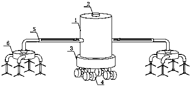
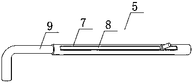
[0028] See Figure 1-7 As shown, a watering device used for corn after sowing includes a water tank 1, an electric roller 4, a water delivery tray 5, a watering rack 6 and a pouring tray 19, four electric rollers 4 are arranged under the water tank 1, and the water tank 1 A power distribution box 3 is arranged between the electric roller 4 and both ends of the water tank 1 are provided with a water supply tray 5, and a watering rack 6 is provided under the water supply tray 5, and the side walls of both ends of the water tank 1 are provided with a water supply tray 5 Matching water receiving port 13; a mounting ring 7 is horizontally arranged on the water supply tray 5, and a chute 8 is horizontally arranged on the mounting ring 7, and a water pipe 9 is clamped inside the mounting ring 7; the upper middle part of the watering rack 6 is provided for convenience and communication The connecting block 15 to which the water pipe 9 is connected, and the connecting block 15 is provide...

Embodiment 2

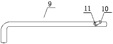
[0030] In addition, please continue to see Figure 2-7 As shown, the difference from the above-mentioned embodiment is that a water-filling cover 2 is screwed on the upper middle of the water tank 1, and the water tank 1 is filled with water through the water-filling cover, and the outer ring of the water tank 1 is laid with a sealing plate 14 to prevent water leakage. The water pipe 9 is vertically provided with a sliding clip post 10, and the sliding clip post 10 is screwed with a tightening bolt 11, and the extension of the water pipe 9 is changed by sliding the sliding clip post 10 back and forth on the chute 8 of the ring 7 Length, thereby changing the working position of the two watering racks 6, so that the overall watering position and overall width of the device are changed, so that the device is more accurate in the watering position of the ground. The sliding clamp post 10 penetrates the chute 8 and is sliding The diameter of the clamping post 10 matches the width of...


PUM


Abstract

The invention discloses an irrigating device after corn planting, which comprises a water tank, a water holding cover, a power distribution box, an electric roll wheel, a water delivering disk, watering frames, a mounting ring, a chute, a water connecting pipe, a slide buckle pillar, a screwing bolt, a water cabin, a water receiving opening, a sealing plate, a connecting block, a water connectinghole, a water dividing disk, a motor, a rotary pouring disk, a sheathing disk, a watering rod, a driving gear, a sleeve block and a water outlet. The irrigating device has the beneficial effect that the device is high in automatic degree in use, free from labor operation, and saves time and force and guarantees the using convenience. People can change the extending length of the water connecting pipe by gliding the slide buckling pillar forwards and backwards on the chute of the mounting ring upon the watering demand of corn planting lands with different widths, thus the working positions of two watering frames can be changed, the watering position and the overall width of the whole device are changed; the device has more accurate soil watering position, the adaption universality is guaranteed; the device is convenient to operate, and every member is flexible in connection.

Description

Technical field [0001] The invention relates to a watering device, in particular to a watering device used after corn sowing, and belongs to the technical field of agricultural machinery application. Background technique [0002] After the corn is sowed, the sown land is often dry and lack of water. The watering device is used very frequently after the corn is sowed. Its main function is to water the sown land to make the land softer and more watery and to ensure the growth of corn seeds. Grow faster. [0003] The current watering devices used for corn after sowing still have many shortcomings. The existing watering devices used for corn after sowing have insufficient watering of the sown land, and the watering efficiency is poor. When the device is in use, it requires continuous manpower control, which is time-consuming and labor-intensive, and not convenient enough. It is not possible to adjust the overall working width of the device according to the width of the ground to be ir...

Claims


Application Information

Patent Timeline
Patent Type & Authority Applications(China)
IPC IPC(8): A01G25/09
CPCA01G25/09
Inventor 周丽珠陈明江
Owner 防城港市绿华源农林科技有限公司
Why Eureka
Try Eureka