Fixed grate incinerator

A technology for fixing grate and incinerator, applied in incinerator, combustion method, combustion type, etc., can solve problems such as "stick", excessive thermal expansion of blades, and the impact of incinerator production interests, so as to achieve reliable and stable work and material incineration. Increased efficiency, avoiding overheating expansion and seizing of the shaft

Inactive Publication Date: 2018-04-13
王志斌
View PDF6 Cites 0 Cited by
  • Summary
  • Abstract
  • Description
  • Claims
  • Application Information

AI Technical Summary

Problems solved by technology

When the blade turns over and passes through the gap of the fixed grate next time, it often happens that the blade thermally expands too wide and "stuck" in the above gap, which causes the incinerator, which has been continuously incinerated all the year round, to have to be shut down frequently for maintenance, thus causing great harm to the incinerator manufacturer. have a huge impact on the actual production benefits of

Method used


Image

  • Fixed grate incinerator
  • Fixed grate incinerator
  • Fixed grate incinerator

Examples


Embodiment Construction

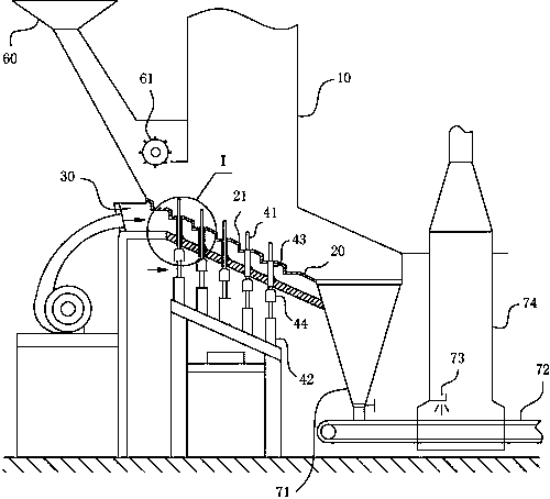
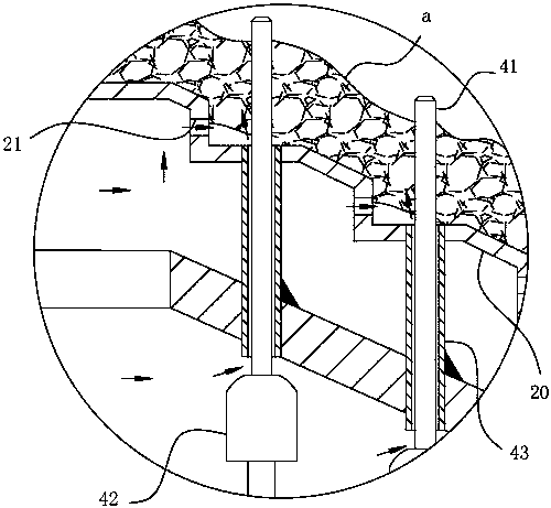
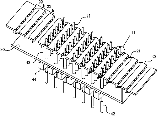
[0036] For ease of understanding, combined here Figure 1-4 Specifically set forth the component structure of the present invention and its concrete workflow:

[0037] Concrete structure of the present invention, refer to figure 1 Shown, comprise main combustion chamber 10 and be positioned at the fixed fire grate 10 in main combustion chamber 10, the hot air chamber 30 that communicates with external air supply assembly is arranged below main combustion chamber 10. Fixed furnace 20 rows of surfaces are inclined up and down from the feed end to the slag discharge end to form a slope, and the horizontal platform stage 22 is set in sections on the slope surface of its row body. At the straight plate place of horizontal platform stage 22, add the horizontal shape ventilation hole 21 that many communicate with hot blast chamber 30 and main combustion chamber 10, all hot blasts all enter main combustion chamber 10 from ventilation hole 21 in the hot blast chamber 30 to promote mat...


PUM


Abstract

The invention belongs to the field of garbage incineration equipment and particularly relates to a fixed grate incinerator. The fixed grate incinerator at least comprises a main combustion chamber anda fixed grate. The plate surface of the fixed grate is obliquely arranged. The high end of the fixed grate constitutes the material input end. The lower end of the fixed grate constitutes the ash residue outlet end for ash residues formed by incinerating materials. The ash residue outlet end communicates with an ash discharge assembly. A hot air chamber is arranged below the main combustion chamber. A hot air supply path is through in the fixed grate. The fixed grate incinerator further comprises push rods and power parts. The push rods penetrate through a material layer on the fixed grate atthe maximum lift. A push rod assembly further comprises shaft sleeves with a preset length. One end of each shaft sleeve penetrates through the fixed grate in the movement direction of the corresponding push rod and is fixedly connected to the fixed grate. Ventilation gaps for allowing air to pass through are formed between the shaft sleeves and the corresponding push rods. The other ends of theshaft sleeves communicate with an external environment and / or an air-cooling chamber. The fixed grate incinerator is high in material incineration efficiency and good in assembly working reliability,and the service life of the fixed grate incinerator can also be effectively prolonged.

Description

technical field [0001] The invention belongs to the field of waste incineration equipment, and in particular relates to a fixed grate incinerator with excellent wind circulation capability, high service life and low maintenance frequency. Background technique [0002] With the rapid development of production and the rapid rise of the economy, my country has entered the ranks of countries with high production of urban domestic waste. According to statistics, in 1990, the total output of urban garbage in China was 69 million tons, among which the garbage output in Shanghai was 2.7 million tons (about 7,500 tons per day), ranking first in the country. As of 2014, the annual stockpiling of garbage in the country has reached more than 6 billion tons, occupying as much as 500 million m2 (750,000 mu) of land. Among the more than 600 cities in the country, more than 200 have been surrounded by garbage mountains. There are nearly 2,000 garbage dumps over 50m2 within 1,260km2 of urb...

Claims


Application Information

Patent Timeline
IPC IPC(8): F23G5/00F23G5/44
CPCF23G5/002F23G5/44
Inventor 王志斌陈玉琴黄婷婷邢涛程永伟
Owner 王志斌
Why Eureka
Try Eureka