
Heating and cooling module and blower

A blower, cooling and heating technology, applied in the field of cooling and heating modules and blowers, can solve the problem of reducing the performance of the cooling and heating module 10, and achieve the effect of preventing low performance

Active Publication Date: 2018-04-13
(株)恩艾思进
View PDF17 Cites 6 Cited by
  • Summary
  • Abstract
  • Description
  • Claims
  • Application Information

AI Technical Summary

Problems solved by technology

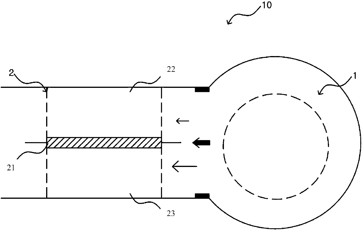
[0010] The above-mentioned dew condensation on the cooling side greatly reduces the performance of the heating and cooling module 10

Method used


Image

  • Heating and cooling module and blower
  • Heating and cooling module and blower
  • Heating and cooling module and blower

Examples


Embodiment Construction

[0054] The present invention will be described in detail below in conjunction with specific embodiments. The following examples will help those skilled in the art to further understand the present invention, but do not limit the present invention in any form. It should be noted that those skilled in the art can make several changes and improvements without departing from the concept of the present invention. These all belong to the protection scope of the present invention.

[0055] In order to fully understand the present invention, its operational advantages, and objects achieved by implementing the present invention, reference should be made to the drawings illustrating preferred embodiments of the present invention and the contents described in the drawings.

[0056]The terms used in this specification are used only to describe a specific example, and are not intended to limit the present invention. A singular expression includes plural expressions as long as it is not c...


PUM


Abstract

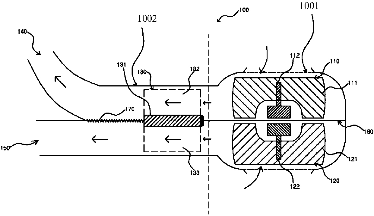
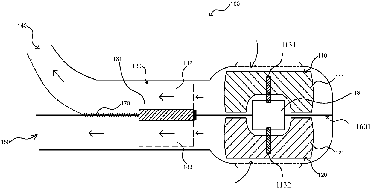
A heating and cooling module using a thermoelectric module is disclosed. The heating and cooling module includes a thermoelectric module; a first impeller for sucking outside air and blowing air to afirst flow path passing through a cooling side of the thermoelectric module; and a second impeller for sucking outside air and blowing air to a second flow path passing through a heating side of the thermoelectric module, and the air blown by the first impeller is moved only to the first flow path.

Description

technical field [0001] The invention relates to a cooling and heating module and a blower using thermoelectric elements. Background technique [0002] Thermoelectric modules using thermoelectric elements (e.g., Peltier thermoelectric elements) are used in heating and cooling equipment, cooling equipment, and refrigeration equipment, and have recently been used in home and business refrigerators, small refrigerators for vehicles, and can coolers Various devices that use electricity to provide cooling or heating, such as heating and cooling devices for car seats. [0003] As is well known, a thermoelectric module includes: a pair of insulating plates, a plurality of thermoelectric elements (a plurality of P-type thermoelectric semiconductor elements and N-type thermoelectric semiconductor elements) disposed between the insulating plates and electrically connected in series, Heat transfer media (for example, heat transfer plates, heat transfer pins, heat sinks, etc.) respectiv...

Claims


Application Information

Patent Timeline
Patent Type & Authority Applications(China)
IPC IPC(8): F04D25/08F04D25/16F04D29/58F24F5/00F24F3/14
CPCF04D25/08F04D25/16F04D29/582F24F3/1411F24F5/0042
Inventor 金书莹崔恒哲
Owner (株)恩艾思进
Learn More