Height-adjustable high-strength rebar bracket

A technology of high-strength steel bars and steel bar brackets, applied in building reinforcements, structural elements, building components, etc., can solve problems such as easy mold escape, fragility, and hidden quality problems, and achieve the effect of ensuring reliability and improving reliability

Pending Publication Date: 2018-04-13
苏州市相城区建设工程质量监督站
View PDF6 Cites 1 Cited by
  • Summary
  • Abstract
  • Description
  • Claims
  • Application Information

AI Technical Summary

Problems solved by technology

The steel bar bracket overcomes the disadvantages of the cement block being fragile, difficult to transport, and high cost, and avoids the easy escape of the formwork during the concrete pouring process, the insecure fixation of the steel bar, and the common uneven phenomenon when the formwork is removed, which solves the problem of concrete Due to small cracks in the components, it is easy to cause engineering hidden dangers, which cannot guarantee the quality of the project
[0003] Because steel bar supports have the above-mentioned many advantages, they are widely used in the construction industry. However, the current steel bar supports are found to have the following problems when they are used: 1. Due to the different requirements for the thickness of the steel bar protection layer in different buildings, the existing steel bar supports are different. It has the height-adjustable function of the upper and lower rows of bars, so the applicability is poor; 2. In the existing steel bar support, the upper and lower rows of bars are fixed to them by binding, which has the problems of troublesome fixing, time-consuming and laborious problems, and cannot Ensure the parallelism of the upper and lower rows of bars; 3. The positioning reliability of the upper and lower rows of bars and the steel support is not good, and there are certain quality risks

Method used


Image

  • Height-adjustable high-strength rebar bracket
  • Height-adjustable high-strength rebar bracket
  • Height-adjustable high-strength rebar bracket

Examples


Embodiment

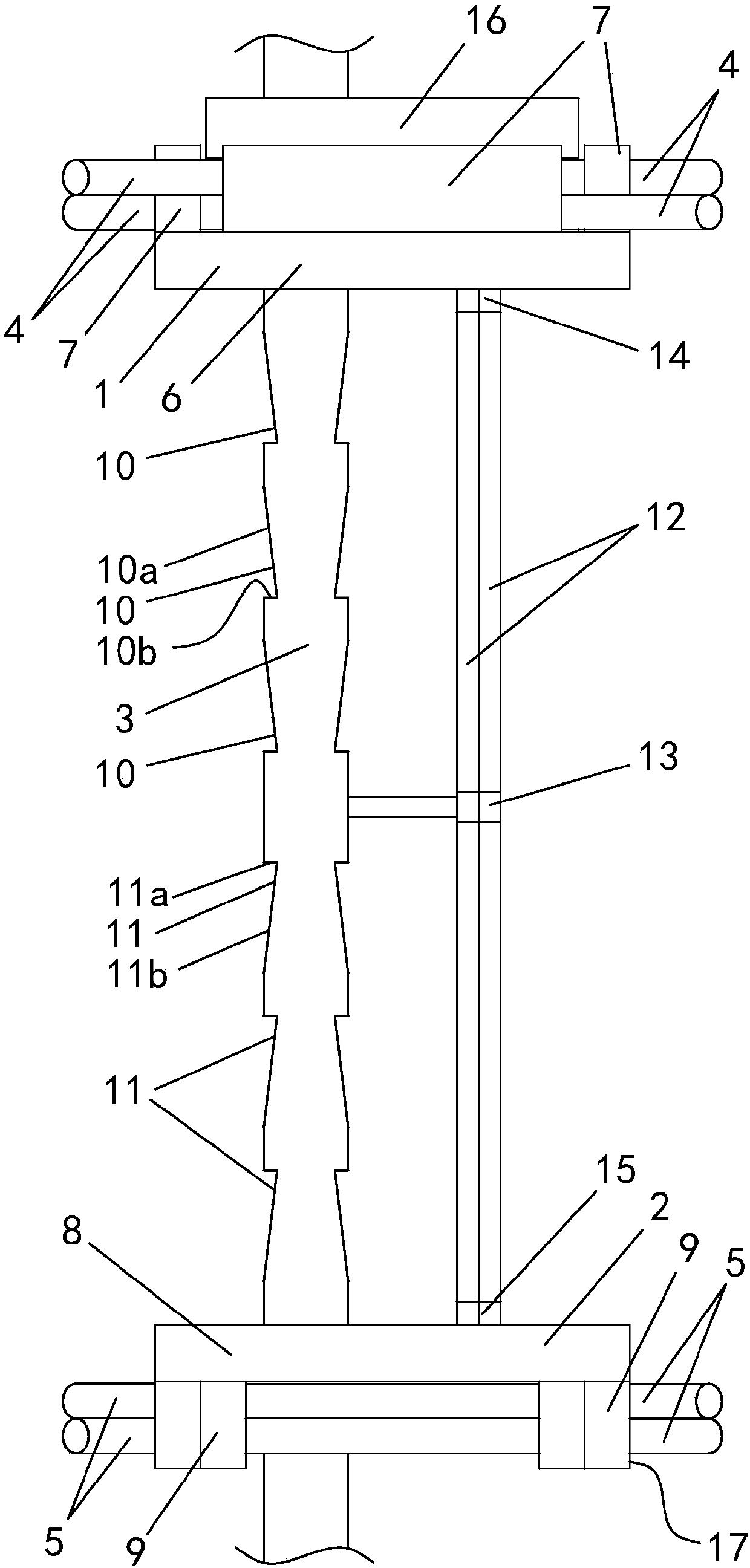
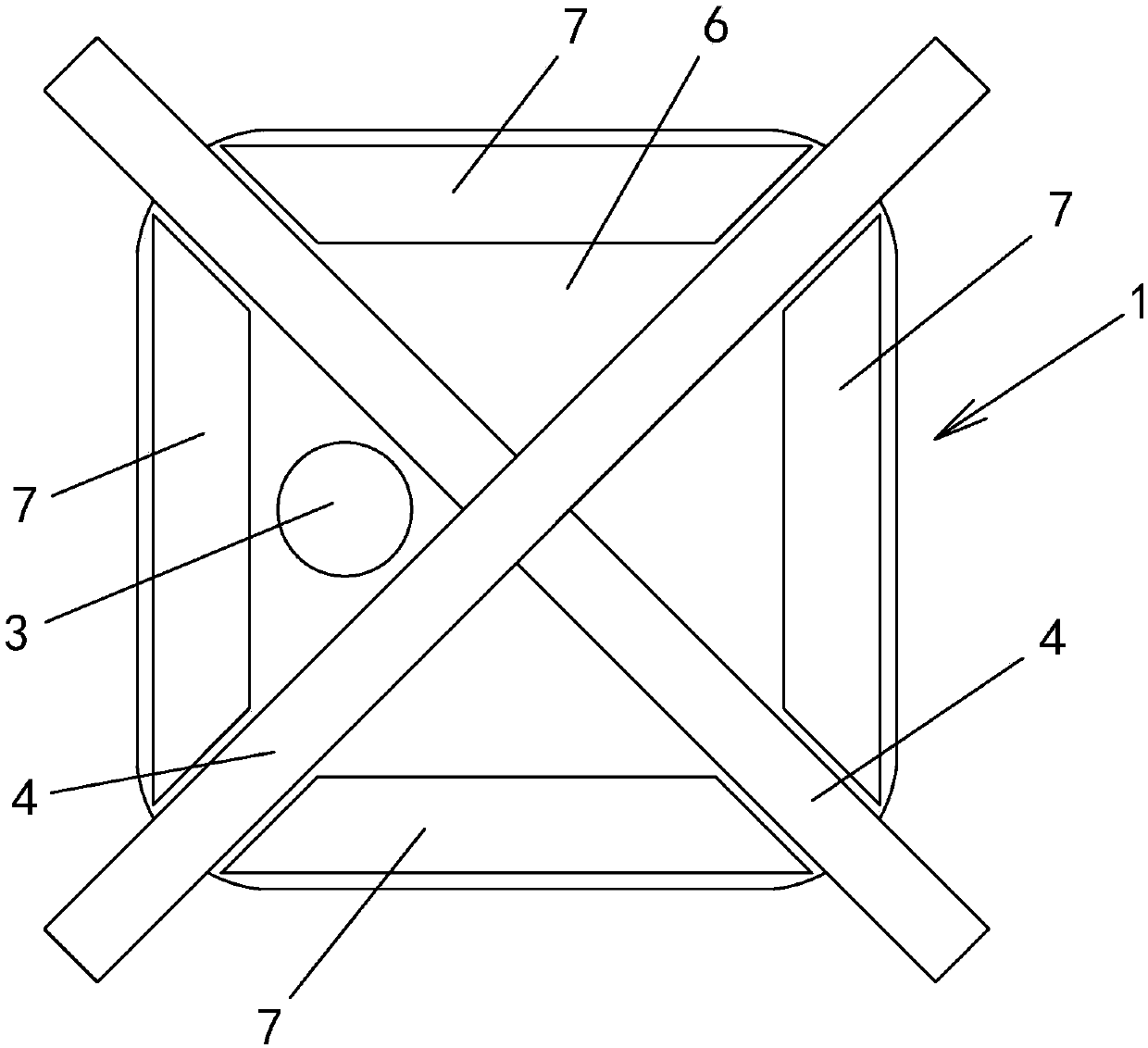
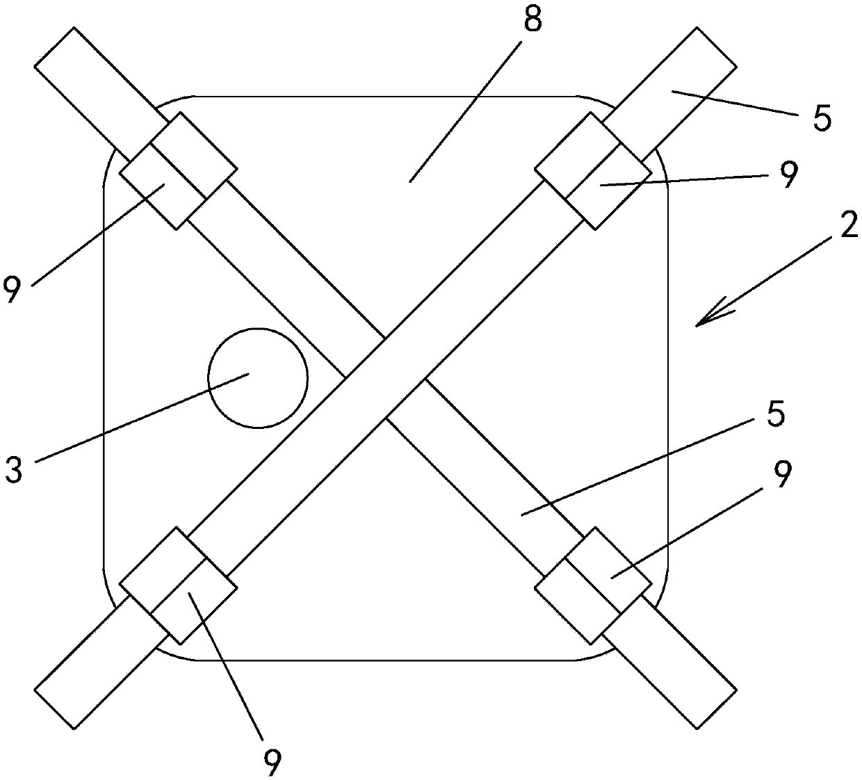
[0040] Example: see attached Figure 1~4 As shown, a height-adjustable high-strength steel bar support includes an upper positioning frame 1, a lower positioning frame 2 and a pillar 3; the upper positioning frame 1 is used for positioning the upper rib 4, and the lower positioning frame 2 is used for Locate the lower row of ribs 5, and the upper positioning frame 1 and the lower positioning frame 2 are all height-adjustably positioned on the pillar 3; through the height-adjustable design, the distance between the upper positioning frame 1 and the lower positioning frame 2 can be changed , and then change the spacing between the upper row of bars 4 and the lower row of bars 5, so that the steel bar bracket can adapt to different steel bar cover thickness requirements.

[0041] The upper positioning frame 1 includes a supporting plate 6, the plate body of the supporting plate 6 is arranged horizontally, and the circumference of the supporting plate 6 protrudes upwards with a pl...


PUM


Abstract

A height-adjustable high-strength rebar bracket comprises an upper positioning frame, a lower positioning frame and a supporting column. The upper positioning frame and the lower positioning frame areboth positioned to the supporting column in a height-adjustable mode, the upper positioning frame comprises a supporting plate, and a plurality of positioning hooks are arranged at the peripheral part of the supporting plate in a protruding mode, and used for positioning an upper row of rebars; the lower positioning frame comprises a top plate, a plurality of elastic positioning claws are arranged on the lower portion of the peripheral part of the top plate in a protruding mode, and used for positioning a lower row of rebars, a plurality of positioning grooves are formed in the supporting column in a sunken mode, the upper positioning grooves are used for being in snap fit with the supporting plate of the upper positioning frame, and used for fixing the upper positioning frame to the different height positions of the supporting column, the upper edges of the upper positioning grooves tilt upwards and outwards, and the lower edges are horizontally arranged, and are perpendicular to theouter edge of the supporting column to be in an annular shape; and the lower positioning grooves are used for being in snap fit with the top plate of the lower positioning frame and fixing the lowerpositioning frame to the different height positions of the supporting column, the upper edges of the lower positioning grooves are horizontally arranged, and are perpendicular to the outer edge of thesupporting column to be in an annular shape, and the lower edges tilt downwards and outwards. According to the height-adjustable high-strength rebar bracket, the spacing between the upper row of rebars and the lower row of rebars can be flexibly adjusted, and the fixing difficulty between the upper row of rebars and the rebar bracket as well as between the lower row of rebars and the rebar bracket is reduced.

Description

technical field [0001] The invention relates to the construction industry, in particular to a height-adjustable high-strength steel bar support. Background technique [0002] Rebar supports are used in the construction field to support steel bars, control the spacing of steel bars and the thickness of the cover in concrete members. The steel bar bracket overcomes the disadvantages of the cement block being fragile, difficult to transport, and high cost, and avoids the easy escape of the formwork during the concrete pouring process, the insecure fixation of the steel bar, and the common uneven phenomenon when the formwork is removed, which solves the problem of concrete The components are prone to engineering hidden dangers due to small cracks, and it is difficult to guarantee the quality of the project. [0003] Because the steel support has the above-mentioned many advantages, it is widely used in the construction industry. However, the current steel support has the follow...

Claims


Application Information

Patent Timeline
IPC IPC(8): E04C5/20
CPCE04C5/206
Inventor 朱逢斌
Owner 苏州市相城区建设工程质量监督站
Why Eureka
Try Eureka