A kind of automatic ejector device with time delay function and mold having the same

An automatic ejection and functional technology, applied in electric vehicles, vehicle energy storage, transportation and packaging, etc., can solve problems such as long research and processing time, inconvenient assembly and replacement, large overall size of the mold, etc., to achieve no collision Hidden dangers of the mold, convenient assembly and replacement, and the effect of ensuring quality and pass rate

Active Publication Date: 2022-07-05
张海勇
View PDF14 Cites 0 Cited by
  • Summary
  • Abstract
  • Description
  • Claims
  • Application Information

AI Technical Summary

Problems solved by technology

The disadvantages of the existing ejection device are long research and processing time, inconvenient assembly and replacement, and the overall size of the mold is large, the cost is very high, and there may be hidden dangers of mold collision

Method used


Image

  • A kind of automatic ejector device with time delay function and mold having the same
  • A kind of automatic ejector device with time delay function and mold having the same
  • A kind of automatic ejector device with time delay function and mold having the same

Examples


Embodiment 1

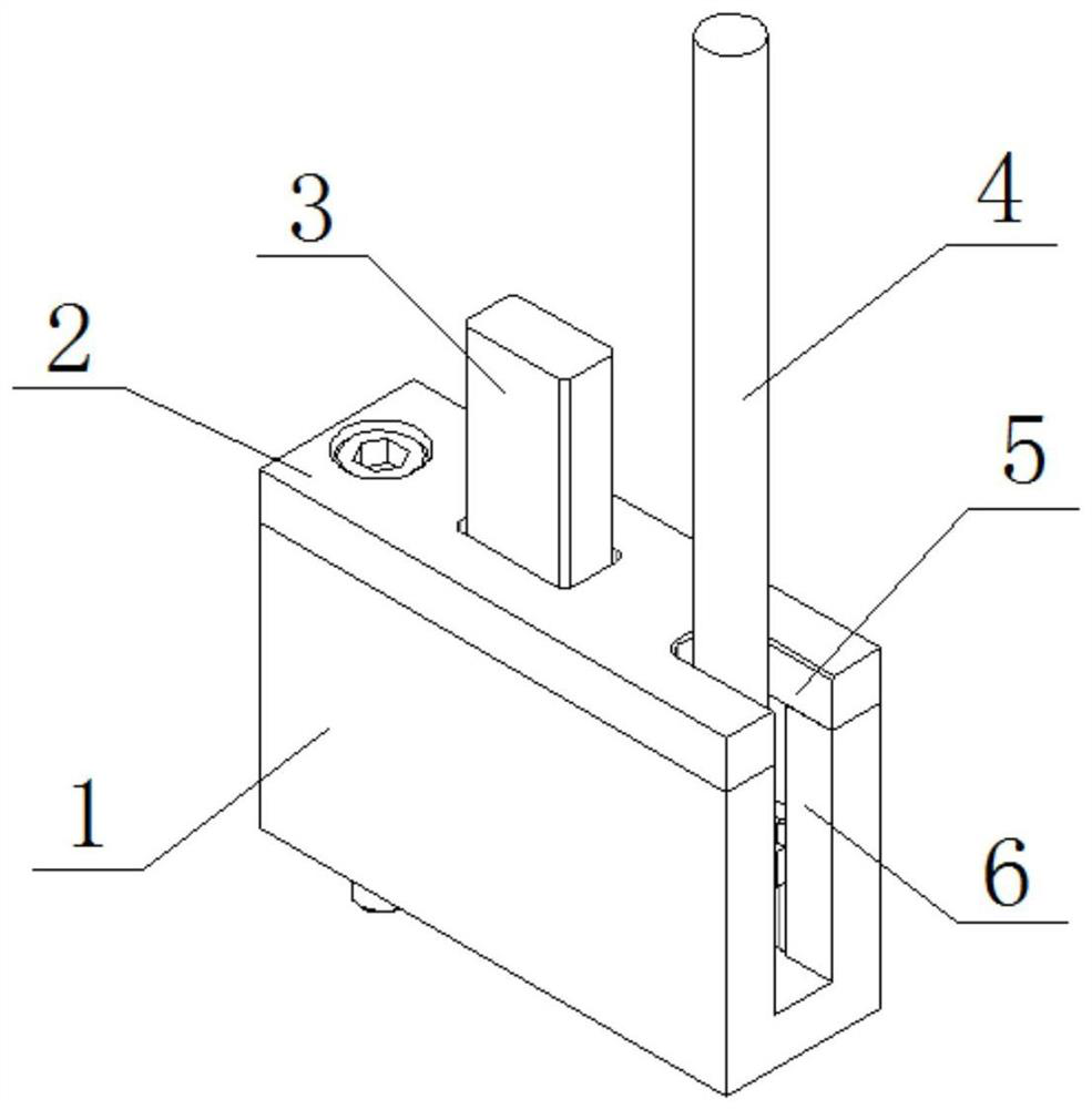
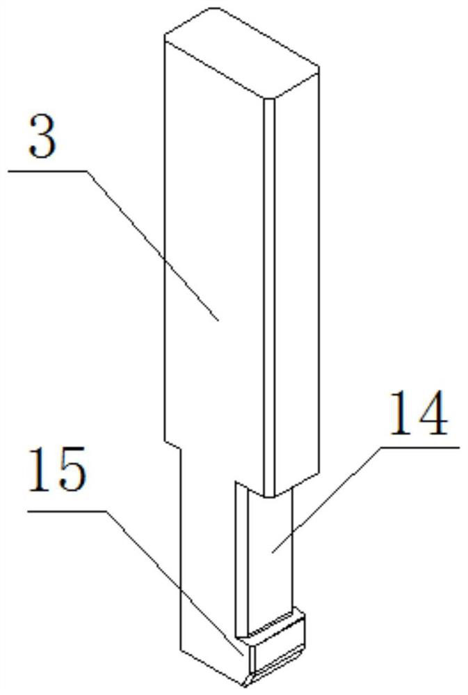
[0039] like Figure 1 to Figure 8 As shown, this embodiment provides an automatic ejection device with a delay function, including a base 1, an upper cover 2, a pressing block 3, a dial 8, a locking block 12 and an ejector 4, and the upper cover 2 is fixedly arranged on the On the base 1, the upper cover 2 is welded on the upper surface of the base 1, the base 1 is provided with a placement groove 10, the dial block 8 is set in the placement groove 10, the upper cover 2 is provided with a pressure block mounting hole 9, and the dial block 8 is provided with A pressure block guide hole 13 and a lock block guide hole 20 are provided, the lower end of the pressure block 3 is arranged through the pressure block guide hole 13, the upper end of the pressure block 3 is arranged through the pressure block installation hole 9, and the lock block 12 is arranged in the lock block guide hole 20, The pressure block guide hole 13 and the lock block guide hole 20 communicate with each other,...

Embodiment 2

[0051] like Figure 3 to Figure 10 As shown, this embodiment provides an automatic ejection device with a delay function, including a base 1, an upper cover 2, a pressing block 3, a dial 8, a locking block 12 and an ejector 4, and the upper cover 2 is fixedly arranged on the On the base 1, the upper cover 2 is welded on the upper surface of the base 1, the base 1 is provided with a placement groove 10, the dial block 8 is set in the placement groove 10, the upper cover 2 is provided with a pressure block mounting hole 9, and the dial block 8 is provided with A pressure block guide hole 13 and a lock block guide hole 20 are provided, the lower end of the pressure block 3 is arranged through the pressure block guide hole 13, the upper end of the pressure block 3 is arranged through the pressure block installation hole 9, and the lock block 12 is arranged in the lock block guide hole 20, The pressure block guide hole 13 and the lock block guide hole 20 communicate with each other...


PUM


Abstract

The invention provides an automatic ejection device with a delay function and a mold having the same, comprising a base, an upper cover, a pressing block, a dial, a locking block and an ejecting piece, the upper cover is fixedly arranged on the base, and the base is arranged There is a placement slot, the dial block is set in the placement groove, the upper cover is provided with a press block installation hole, the dial block is provided with a press block guide hole and a lock block guide hole, the lower end of the press block is arranged through the press block guide hole, and the upper end of the press block is provided with The installation hole of the pressure block is arranged, the lock block is arranged in the guide hole of the lock block, the guide hole of the pressure block and the guide hole of the lock block are communicated with each other, the lock block is arranged in contact with the pressure block, and one end of the ejection piece is installed on the dial block, and also It includes an elastic piece, the elastic piece is arranged in the guide hole of the lock block, one end of the elastic piece is arranged in the dial block, and the other end of the elastic piece is connected with the lock block. It can reduce the overall size of the mold, remove the ejector plate, oil cylinder, push plate and other devices that rely on external force to release the mold, reduce production costs, shorten research and processing time, easy assembly and replacement, and no hidden danger of mold collision.

Description

technical field [0001] The invention relates to the technical field of injection moulds, in particular to an automatic ejection device with a delay function and a mould having the same. Background technique [0002] Plastic products generally complete their molding process by injection molds. The manufacturing process is generally to first inject the melt into the cavity of the injection mold, then cool and form, and then open the mold to eject the product from the injection mold by the ejection structure in the mold, so that the product is completely demolded. In the process of product ejection, it is necessary to protect the integrity of the product as much as possible so that it has a better molding effect. [0003] Most of the existing ejector devices use air cylinders or oil cylinders to drive the ejector plate or the pusher to move up and down, and the ejector plate then drives the pusher or the pusher to move up and down through the push rod. , and then the dial blo...

Claims


Application Information

Patent Timeline
Patent Type & Authority Patents(China)
IPC IPC(8): B29C45/40
CPCB29C45/4005Y02T10/7072
Inventor 张锦泽张海勇
Owner 张海勇
Why Eureka
Try Eureka