
Mother-son fixture feeding and discharging equipment with robot and using method of mother-son fixture feeding and discharging equipment

A robot and sub-fixture technology, applied in metal processing, etc., can solve the problems that robot fixtures cannot adapt to mixed production, waste production man-hours, and unsatisfactory automation, so as to reduce labor costs and error rates, improve production efficiency, and improve The effect of production efficiency and precision

Inactive Publication Date: 2018-04-13
GUANGDONG LXD ROBOTICS CO LTD
View PDF8 Cites 5 Cited by
  • Summary
  • Abstract
  • Description
  • Claims
  • Application Information

AI Technical Summary

Problems solved by technology

[0002] In the past, the loading and unloading of machine tools was done manually. Now, robots are gradually implemented instead of manual loading and unloading operations. However, a single robot fixture cannot adapt to mixed material production. It is still necessary to manually replace machine tool chucks and robot fixtures when changing models and lines. , the degree of automation of such production equipment is not ideal, wasting production man-hours, and there are potential safety risks in manual operation

Method used


Image

  • Mother-son fixture feeding and discharging equipment with robot and using method of mother-son fixture feeding and discharging equipment
  • Mother-son fixture feeding and discharging equipment with robot and using method of mother-son fixture feeding and discharging equipment
  • Mother-son fixture feeding and discharging equipment with robot and using method of mother-son fixture feeding and discharging equipment

Examples


Embodiment Construction

[0026] The present invention will be further described below in conjunction with the accompanying drawings and embodiments.

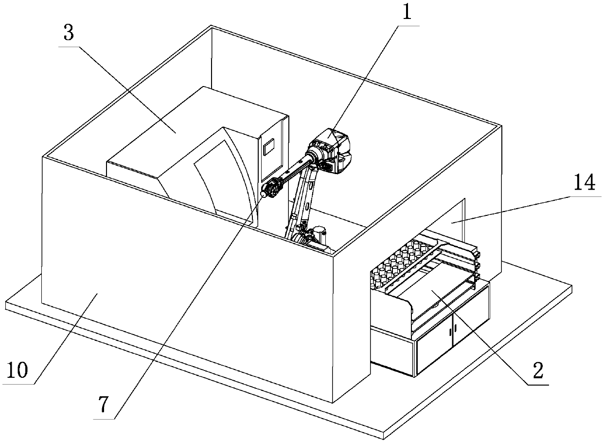
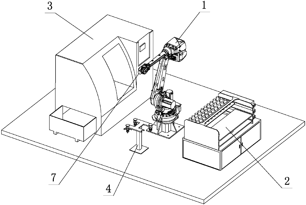
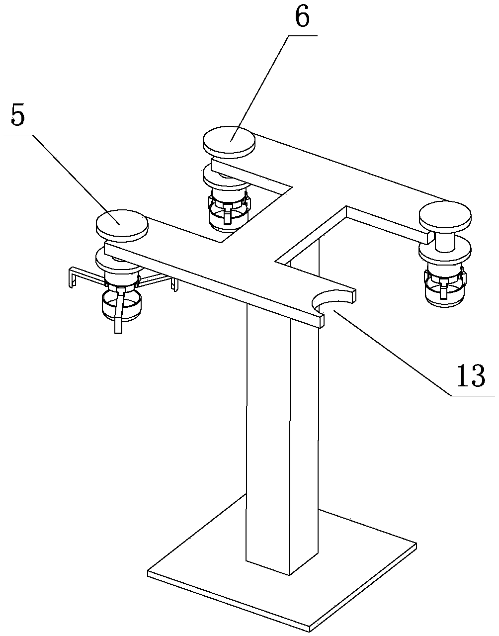
[0027] see Figure 1-Figure 5 , the loading and unloading equipment of the master fixture with a robot, including a robot 1, a loading and unloading table 2 and a machine tool 3, a chuck 8 and a workpiece 9 are placed on the loading and unloading table 2, and the robot 1 moves back and forth between the loading and unloading table 2 and the machine tool 3, and a female fixture 7 is arranged on it, and the side of the robot 1 is also provided with a fixture quick-change frame 4, on which a chuck sub-fixture 5 and a workpiece sub-fixture 6 are placed, and the machine tool 3 is provided with The chuck sub-fixture 5; the robot 1 is conveyed back and forth through the mother fixture 7 and switches the chuck sub-fixture 5 on the loading and unloading table 2 and the machine tool 3; the robot 1 is replaced on the fixture quick change rack 4 through the mother ...


PUM


Abstract

Disclosed is mother-son fixture feeding and discharging equipment with a robot and a using method of the mother-son fixture feeding and discharging equipment. The mother-son fixture feeding and discharging equipment comprises the robot, a feeding and discharging table and a machine tool. A chuck and a workpiece are placed on the feeding and discharging table. The robot moves back and forth betweenthe feeding and discharging table and the machine tool and is provided with a mother fixture. The side part of the robot is further provided with a fast fixture switching frame. A chuck son fixture and a workpiece son fixture are placed on the fast fixture switching frame. The machine tool is provided with the chuck son fixture. The robot conveys and switches the chuck son fixture on the feedingand discharging table and the machine tool back and forth through the mother fixture. The robot reloads the workpiece son fixture on the fast fixture switching frame through the mother fixture, conveys the workpiece on the feeding and discharging table through the workpiece son fixture to the machine tool to complete feeding operation, and conveys the workpiece machined on the machine tool to thefeeding and discharging table to complete discharging operation. The mother-son fixture feeding and discharging equipment with the robot has the characteristics of being simple and reasonable in structure, excellent in performance, convenient to operate, low in manufacturing cost, easy to produce, easy to realize, full-automated, intelligent, high in production efficiency, safe, reliable and the like.

Description

technical field [0001] The invention relates to a loading and unloading device for sub-mother clamps with a robot and a use method thereof. Background technique [0002] In the past, the loading and unloading of machine tools was done manually. Now, robots are gradually implemented instead of manual loading and unloading operations. However, a single robot fixture cannot adapt to mixed material production. It is still necessary to manually replace machine tool chucks and robot fixtures when changing models and lines. , the degree of automation of such production equipment is not ideal, and the production man-hours are wasted. At the same time, there are potential safety risks in manual operation. Therefore, it is necessary to improve and optimize the loading and unloading equipment of robot machine tools to meet the needs of modern production. Contents of the invention [0003] The object of the present invention is to provide a simple and reasonable structure, excellent ...

Claims


Application Information

Patent Timeline
Patent Type & Authority Applications(China)
IPC IPC(8): B23Q7/04
CPCB23Q7/04
Inventor 袁燕何泽贤陈庆烺李云龙
Owner GUANGDONG LXD ROBOTICS CO LTD
Learn More