Method for thermal control multilayer coating of induction type magnetometer

A multi-layer coating and magnetometer technology, which is applied in the direction of the size/direction of the magnetic field, can solve problems such as the inability to fix multi-layer coatings, the inability to overlap adjacent multi-layers, and the impact on the performance of the induction magnetometer.

Active Publication Date: 2018-04-10
AEROSPACE DONGFANGHONG SATELLITE
View PDF5 Cites 3 Cited by
  • Summary
  • Abstract
  • Description
  • Claims
  • Application Information

AI Technical Summary

Problems solved by technology

[0005] (1) It cannot meet the heat insulation requirements. The temperature fluctuation of the induction magnetometer needs to be as small as possible when it is working. Due to its tree-like structure and small size, if the existing coating method is used, relying on the existing tree of the product Shaped configuration for tight wrapping, it is impossible to fix the multi-layer coating with strong glue and Velcro on the product, and it is also impossible to cross-lap adjacent multi-layers, and there is a problem of heat leakage
[0006] (2) It cannot meet the insulation requirements. The working principle of the inductive magnetometer requires that there should be no 360° circumferential conductive loop outside each magnetic antenna
The multi-layer coating itself is composed of double-sided aluminum-coated polyester film and polyester mesh; due to the existence of the aluminum-coated film, the existing wrapping method of wrapping next to the body will form a 360° circumferential conductive pattern outside each magnetic antenna. circuit, affecting the performance of the induction magnetometer
[0007] (3) Unable to meet the equipotential requirements, the inductive magnetometer needs the potential difference between any two points of the external multi-layer coating to be less than 1V during operation
When the inductive magnetometer is running in the orbital space, the outer surface of the multilayer coating will be exposed to the plasma environment, and the space charged particles will deposit on the surface of the coating to generate a potential. Due to the material impedance and insulation requirements, the existing The multi-layer coating method will inevitably produce situations that cannot meet the equipotential requirements

Method used


Image

  • Method for thermal control multilayer coating of induction type magnetometer

Examples


Embodiment

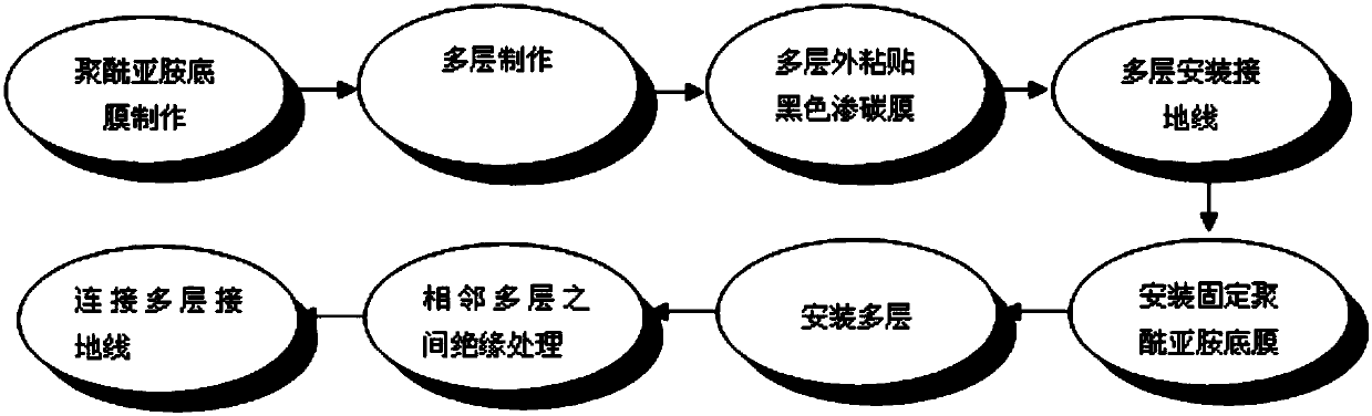
[0045] The implementation steps of this embodiment are specifically as follows:

[0046] 1. First, make the polyimide bottom film

[0047] (1) Place the inductive magnetometer on a piece of white paper with the end of the dendritic sensor as the contact point;

[0048] (2) Draw a triangle with three contact points as vertices on the white paper;

[0049] (3) change the contact point of dendritic sensor end and blank paper, draw all three contact points as the triangle that apex forms successively according to step (2), thus draw the outer contour dimension figure of whole dendritic structure sensor;

[0050] (4) two layers of 100 micron polyimide film materials are pasted together to form a polyimide base film with a thickness of 200 microns;

[0051] (5) Cut the polyimide base film according to the triangle size formed in step (3), and each triangle surface corresponds to a separate polyimide base film.

[0052] 2. Multi-layer production

[0053](1) 20 units of multi-laye...


PUM


Abstract

The invention discloses a method for the thermal control multilayer coating of an induction type magnetometer. The method includes manufacturing a polyimide bottom film, manufacturing multiple layers,pasting a black carburization film outside the multiple layers, installing grounding wires on the multiple layers, installing and fixing the polyimide bottom film, installing the multiple layers, performing insulation processing between adjacent multiple layers, and connecting the grounding wires of the multiple layers. According to the invention, the problem that a traditional method is difficult to carry out coating on a multilayer heat insulation material of a dendritic structure is solved, and the effect that the thermal control multilayer coating meets the requirements of heat insulation, insulation and equipotential of the induction type magnetometer product is achieved.

Description

technical field [0001] The invention relates to thermal control multi-layer coating technology, in particular to a method for thermal control multi-layer coating of an induction magnetometer. Background technique [0002] The induction magnetometer is composed of three mutually perpendicular magnetic antennas (induction coils), which are used to measure the changing magnetic field information within a certain frequency range. Due to the harsh orbital thermal environment in space, when it works in the space orbital environment, in order to ensure its working performance, good thermal protection is required. [0003] At present, the commonly used heat protection method for space orbit is to use multi-layer heat insulation material to carry out multi-layer heat insulation coating for products that need heat protection. The existing coating method is mainly on the regular geometric surface such as plane or cylindrical surface, relying on the configuration of the product itself ...

Claims


Application Information

Patent Timeline
Patent Type & Authority Applications(China)
IPC IPC(8): G01R33/02
Inventor 黎明赵虎宁东坡左颖萍
Owner AEROSPACE DONGFANGHONG SATELLITE
Why Eureka
Try Eureka