Logic control method for electric grounding switch

A logic control and ground knife technology, applied in the electrical field, can solve problems such as unreliable action, danger, and other equipment or on-site staff hazards

Inactive Publication Date: 2018-04-06
ZHONGSHAN MINGYANG ELECTRIC
View PDF6 Cites 0 Cited by
  • Summary
  • Abstract
  • Description
  • Claims
  • Application Information

AI Technical Summary

Problems solved by technology

The drive shaft of the electric ground knife motor drive mechanism is connected with the moving knife head of the ground knife switch, and the ground knife switch is driven to rotate through the drive shaft of the motor, so that the ground knife switch moves in two positions of the closed position and the open position. Therefore, A high level of security implementation is required during the switching process of the two locations, and minor errors during the switching process may cause serious harm
[0003] The traditional electric floor knife operating system generally consists of several control input terminals, and the control input terminals are placed in different locations, there are local positions close to the ground knife, and there are remote positions far from the ground knife. The control signal will be screened. When the staff at the local location is controlling the process, the staff at the remote location also input the control signal, which is likely to be dangerous.
[0004] At the same time, imperfect control logic and unreliable actions may force the motor drive mechanism to run, which may cause harm to other equipment or on-site workers.

Method used


Image

  • Logic control method for electric grounding switch
  • Logic control method for electric grounding switch

Examples


Embodiment Construction

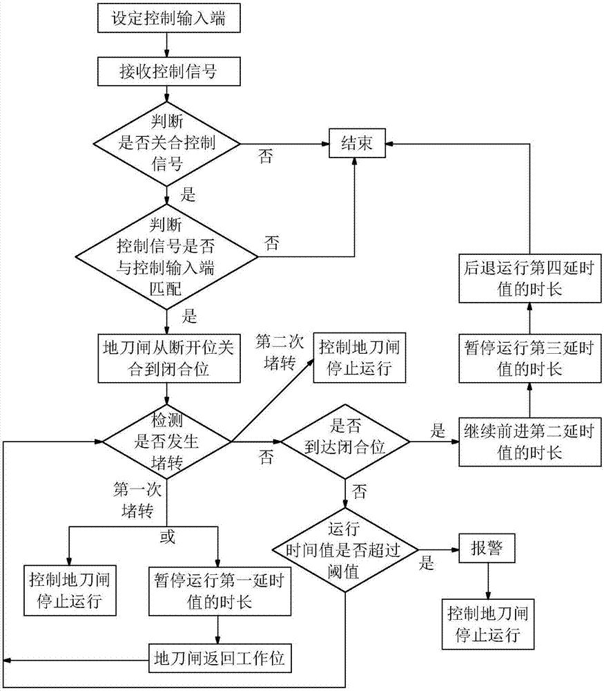
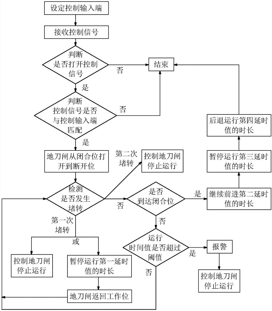
[0022] Such as figure 1 , figure 2 As shown, the logic control method of the electric ground knife of the present invention, the electric ground knife includes a ground knife switch, a main control module, at least two control input terminals and a motor drive mechanism, and the main control module is electrically connected to the control input terminal and the motor drive mechanism respectively. Connection, the motor drive mechanism is connected with the ground knife switch to drive the ground knife switch to move, here there can be multiple control input terminals, set at the local position or a remote position, the main control module includes MCU or CPU and its auxiliary circuits, and the motor drives The drive shaft of the mechanism is connected with one end of the ground knife switch, and the ground knife switch is driven to rotate through the drive shaft of the motor, so that the ground knife switch moves in two positions of a closed position and an open position.

[...


PUM


Abstract

The invention discloses a logic control method for an electric grounding switch. The method comprises the following steps: a control input end is set, and control signals inputted by the set control input end are acquired; a main control module controls a motor driving mechanism to operate to drive the grounding switch to be opened to an opening position from a closing position or to the closing position from an opening position according to the control signals, whether locking happens to the motor driving mechanism is detected, and if locking happens to the motor driving mechanism, the main control module controls the motor driving mechanism to stop operating, or after paused operation for a duration of a first delay value, the grounding switch is then driven to return to the closing position or the opening position; and when the grounding switch reaches the opening position or the closing position, the grounding switch continuously advances for a duration of a second delay value, paused operation of the motor driving mechanism for a duration of a third delay value is carried out, the grounding switch is then driven to be retreated for a duration of a fourth delay time and is thenstopped. Thus, the grounding switch can operate stably, and damages to equipment or even workers can be prevented.

Description

technical field [0001] The invention relates to the electrical field, in particular to a logic control method for electric ground knives. Background technique [0002] According to the requirements of the five defenses, the ground knife needs to be closed during equipment maintenance, which is equivalent to a grounding wire to ensure the personal safety of the maintenance personnel. The drive shaft of the electric ground knife motor drive mechanism is connected with the moving knife head of the ground knife switch, and the ground knife switch is driven to rotate through the drive shaft of the motor, so that the ground knife switch moves in two positions of the closed position and the open position. Therefore, A high level of security implementation is required during the switching process of the two locations, and a slight error in the switching process may cause serious harm. [0003] The traditional electric floor knife operating system generally consists of several contr...

Claims


Application Information

Patent Timeline
Patent Type & Authority Applications(China)
IPC IPC(8): H02H3/02
Inventor 袁红珍戴国权陈立岳丕榜
Owner ZHONGSHAN MINGYANG ELECTRIC
Why Eureka
Try Eureka