


Quick Research
Generate reliable direction feasibility study reports for your R&D in just a few steps.

Technical Q&A
Discover and master advanced knowledge NOW. Basics, ideas, possibilities, all at once.

Find Solutions
As an expert in R&D theories, this can generate solutions to your technical problems instantly.

Evaluate Feasibility
Analyze your overall solution with one click, know your potential R&D risks in advance.

Monitor Landscape
Get weekly tech updates, stay abreast of the latest tech innovations and key insights.
Fault data recording method and apparatus based on avionics devices
A technology of fault data and recording device, applied in the direction of instruments, computer control, simulators, etc., can solve the problems that the system cannot be independently set up temporarily, the difficulty of recording data, and the low degree of generality, so as to quickly locate the fault point and realize the fault location. point, the effect of improving efficiency
- Summary
- Abstract
- Description
- Claims
- Application Information
AI Technical Summary
Problems solved by technology
Method used
Image

Examples
Embodiment 1
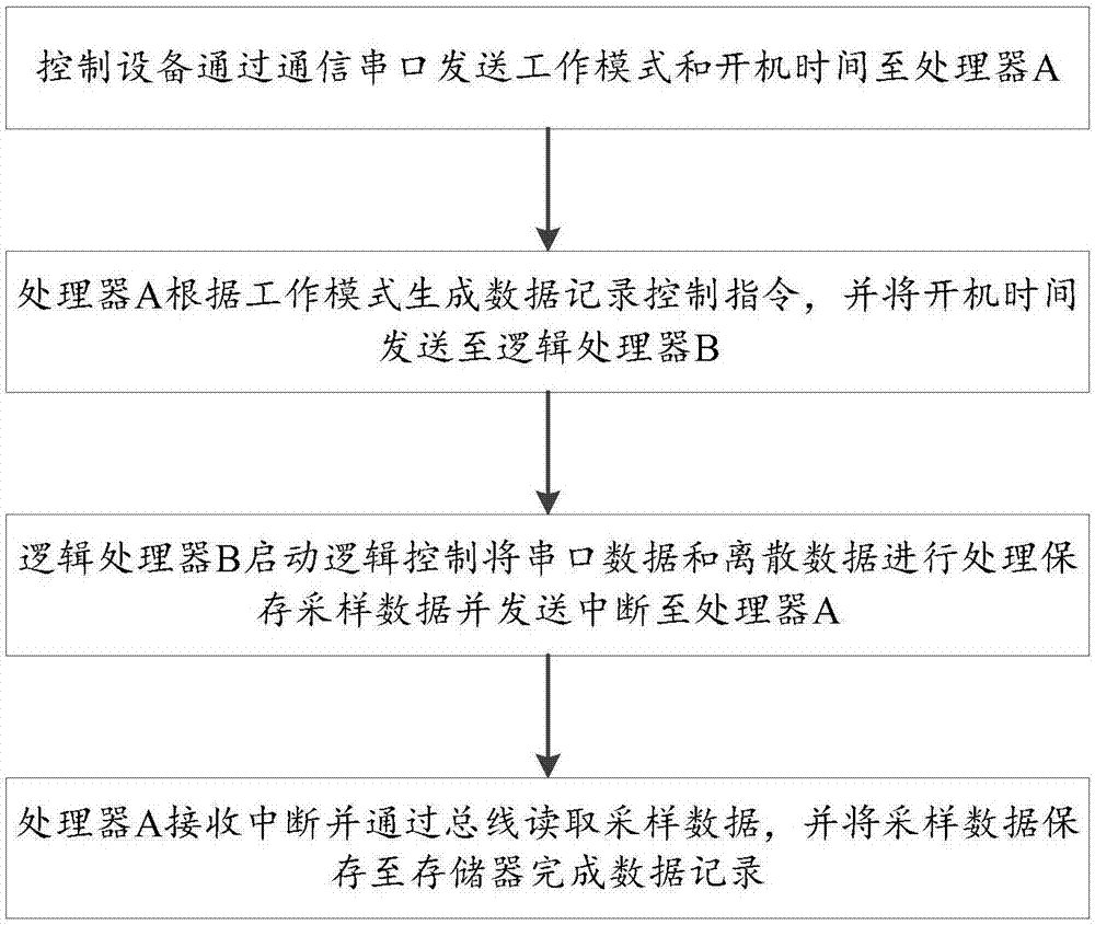
[0032] A fault data recording method based on avionics equipment, comprising the steps of:
[0033] Step 1: The control device sends the working mode and start-up time to processor A through the communication string;
[0034] Step 2: Processor A generates data recording control instructions according to the working mode, and sends the boot time to logical processor B;
[0035] Step 3: Logic processor B starts logic control to process serial port data and discrete data, save sampling data and send an interrupt to processor A;
[0036] Step 4: Processor A receives the interrupt and reads the sampling data through the bus, and saves the sampling data to the memory to complete the data recording.
Embodiment 2
[0038] Methods also include:
[0039] Step 5: Skip to step 2. Processor A generates a data communication control instruction according to the working mode to enter the data communication mode;
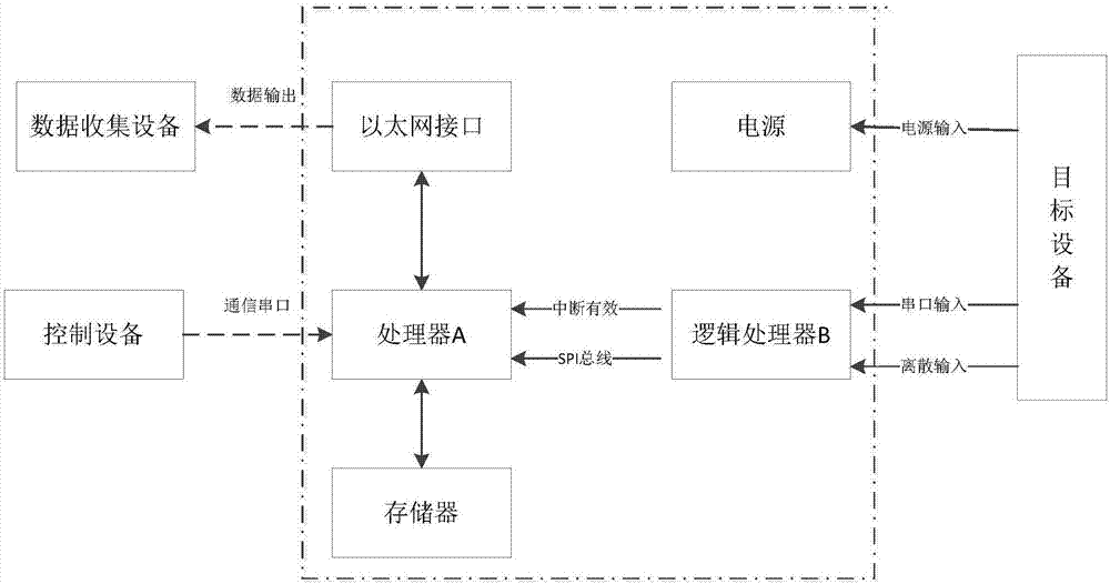
[0040] Step 6: Processor A is connected to the data collection device through the Ethernet interface to complete data output.
Embodiment 3
[0042] A fault data recording device based on avionics equipment, including a control device, a logic processor B, a processor A, a communication serial port, a memory, a bus and a power supply, the control device is connected to the processor A through the communication serial port, and the processor A is connected through the bus It is connected with logical processor B, and the memory is connected with processor A to complete data recording. By setting integrated logic processor B, processor A, control equipment and general peripheral circuits, hardware software is realized, the number of devices is reduced, and the size of the device is reduced. Combined with memory, bus and communication serial port, real-time recording of operating data is realized. .
PUM
 Abstract
Description
Claims
Application Information
 - R&D Engineer
- R&D Manager
- IP Professional
- Industry Leading Data Capabilities
- Powerful AI technology
- Patent DNA Extraction
Browse by: Latest US Patents, China's latest patents, Technical Efficacy Thesaurus, Application Domain, Technology Topic, Popular Technical Reports.
© 2024 PatSnap. All rights reserved.Legal|Privacy policy|Modern Slavery Act Transparency Statement|Sitemap|About US| Contact US: help@patsnap.com