LiDAR, vehicle, ranging error measurement method, and ranging method

A lidar, ranging error technology, applied in the field of vehicle, and ranging, lidar, ranging error measurement, can solve the problems of measurement distance error, different delay and so on

Active Publication Date: 2020-08-07
BYD CO LTD
View PDF5 Cites 0 Cited by
  • Summary
  • Abstract
  • Description
  • Claims
  • Application Information

AI Technical Summary

Problems solved by technology

[0004] The purpose of the present disclosure is to provide a laser radar, a vehicle, a distance measurement error measurement method, and a distance measurement method, which are used to solve the technology that the delay of the two circuit loops in the related laser radar is different, resulting in an error in the measurement distance question

Method used


Image

  • LiDAR, vehicle, ranging error measurement method, and ranging method
  • LiDAR, vehicle, ranging error measurement method, and ranging method
  • LiDAR, vehicle, ranging error measurement method, and ranging method

Examples


Embodiment Construction

[0049] Reference will now be made in detail to the exemplary embodiments, examples of which are illustrated in the accompanying drawings. When the following description refers to the accompanying drawings, the same numerals in different drawings refer to the same or similar elements unless otherwise indicated. The implementations described in the following exemplary examples do not represent all implementations consistent with the present disclosure. Rather, they are merely examples of apparatuses and methods consistent with aspects of the present disclosure as recited in the appended claims.

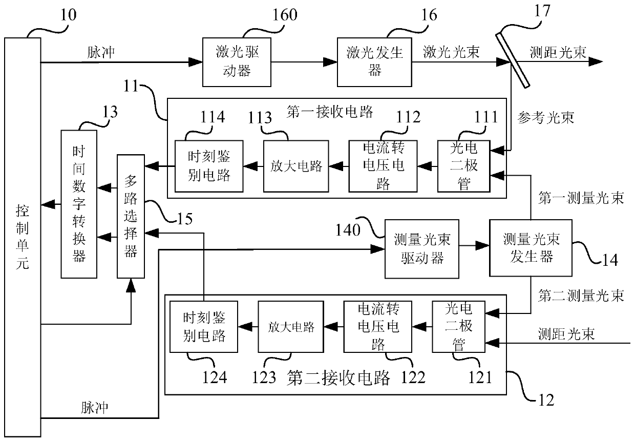
[0050] figure 1 It is a block diagram of a laser radar according to an exemplary embodiment. Such as figure 1 As shown, a laser radar includes a first receiving circuit 11 , a second receiving circuit 12 , a time-to-digital converter 13 , a control unit 10 and a measuring beam generator 14 .

[0051] The measuring beam generator 14 is used for emitting a first measuring beam to the ...


PUM


Abstract

The invention discloses a laser radar, a vehicle, a ranging error measurement method and a ranging method. The laser radar is composed of a first receiving circuit, a second receiving circuit, a time-digital converter, a control unit, and a measuring beam generator. The measuring beam generator is used for transmit a first measurement beam to the first receiving circuit and a second measurement beam to the second receiving circuit simultaneously; the first receiving circuit is used for converting the first measurement beam into a first electric signal; the second receiving circuit is used forconverting the second measurement beam into a second electric signal; and the time-digital converter is used for determining a calibration time difference for correcting a ranging result of the laserradar and transmitting the calibration time difference to the control unit and the control unit stores the information, wherein the calibration time difference is a time difference of arriving at thetime-digital converter by the first electric signal and the second electric signal. Therefore, a technical problem of an error of a measurement distance because of different delays of the two circuitsin the related laser radar is solved.

Description

technical field [0001] The present disclosure relates to the field of radar ranging, and in particular, to a laser radar, a vehicle, a ranging error measurement method, and a ranging method. Background technique [0002] In related technologies, the pulse laser radar technology uses the time-of-flight (TOF: Time-of-Flight) calculation method to measure the distance. In order to improve the measurement accuracy, the emitted beam will be split, and one path will be used as the internal reference optical path, and the other path will be used as the internal reference path. To detect the beam of the measured object, the same receiving circuit will be designed for both beams, so as to reduce the error caused by delay. The time-of-flight measurement method uses the pulse signal received by the internal reference optical path as the start signal of the timing chip TDC (Time ToDigital Converter; time-to-digital converter), and the pulse signal received by the reflected echo beam ref...

Claims


Application Information

Patent Timeline
Patent Type & Authority Patents(China)
IPC IPC(8): G01S17/10G01S7/497
CPCG01S7/497G01S17/10
Inventor 农英雄
Owner BYD CO LTD
Why Eureka
Try Eureka