
Combination wall for demountable and mountable combination house

A combined house, dismantling technology, applied in the direction of walls, building components, buildings, etc., can solve the problems of steel-frame cement board houses and iron-clad houses, poor living environment, inconvenient transportation, use and recycling, etc.

Active Publication Date: 2018-04-06
GUANGDONG XIANGBO ECOLOGICAL TECH CO LTD
View PDF6 Cites 0 Cited by
  • Summary
  • Abstract
  • Description
  • Claims
  • Application Information

AI Technical Summary

Problems solved by technology

[0002] At present, there are many types of detachable combined houses, including steel-structured cement board houses, iron-sheet houses and tents, but they all have certain disadvantages, such as heat insulation problems, which limit their use in winter, especially in the north, or require Provide a large amount of energy for heating; the problem of repeated reuse and recycling, cement prefabricated houses have great limitations in reuse and recycling, and in addition, the weight of steel frame cement board houses and iron sheet houses is relatively large, which also poses problems for transportation, It is inconvenient to use and recycle; comfort problems, living tents often bring people a sense of instability, and the living environment is poor; the problem of low bearing capacity and seismic performance, in order to reduce the weight of detachable modular houses, it is bound to be Its bearing capacity and anti-seismic performance are greatly reduced

Method used


Image

  • Combination wall for demountable and mountable combination house
  • Combination wall for demountable and mountable combination house
  • Combination wall for demountable and mountable combination house

Examples


Embodiment 1

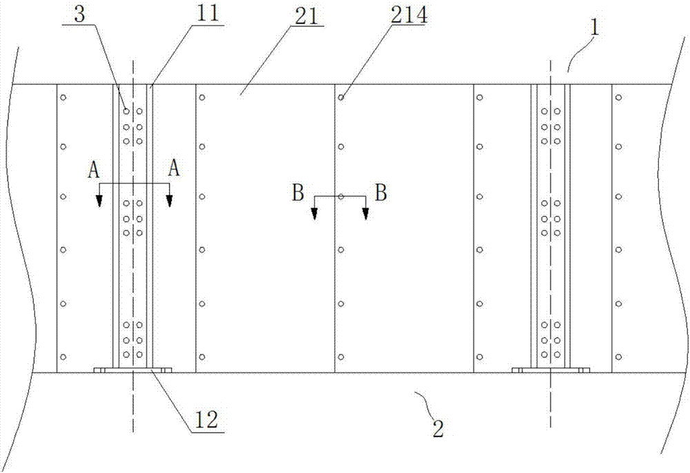
[0031] refer to Figure 1 to Figure 6 , in this embodiment, there is provided a detachable combined wall for a combined house, the combined wall includes at least two combined columns 1 arranged at intervals in the transverse direction, and spliced ​​wall panels combined with the combined columns 1 2.

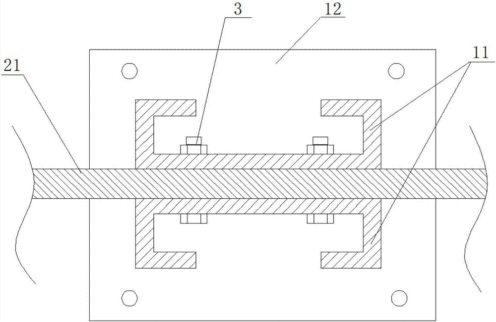
[0032] Specifically, each combined column 1 includes two C-shaped cold-formed thin-walled steel 11 extending along the height direction of the wall, and the openings of the two C-shaped cold-formed thin-walled steels 11 are arranged opposite to each other ( figure 2 It is clearly shown in the figure), preferably, the wall thickness of the C-shaped cold-formed thin-walled steel 11 is in the range of 2-3 mm.

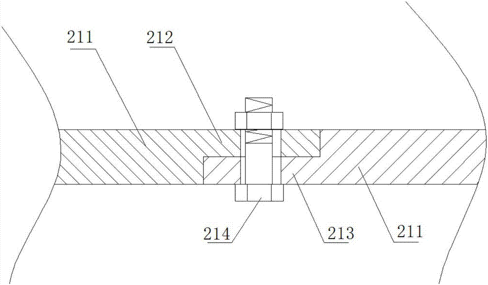
[0033] Specifically, the spliced ​​wall panel 2 includes a plurality of spliced ​​panels 21 that are spliced ​​side by side. combined reference image 3 with Figure 4, each splicing plate 21 extends along the height direction of the wall, and has the same length as ea...


PUM


Abstract

The invention relates to a combination wall for a demountable and mountable combination house. The combination wall comprises combined vertical columns and a spliced wallboard. Each combined verticalcolumn comprises two pieces of C-shaped cold-bent thin-wall sectional steel; the spliced wallboard comprises a plurality of spicing boards arranged transversely side by side; each splicing board comprises a main board part, a first strip-shaped bulge and a second strip-shaped bulge, wherein the two strip-shaped bulges are arranged on the left side edge and the right side edge of the main plate part correspondingly and arranged in a staggered mode along the central face of the main plate part; a line of through holes is formed in each of the first strip-shaped bulges and the second strip-shapedbulges; each first strip-shaped bulge is detachably connected with the second strip-shaped bulge, adjacent to the first strip-shaped bulge, of the corresponding main plate part through fastening pieces penetrating through the corresponding through holes; and each second strip-shaped bulge is detachably connected with the first strip-shaped bulge, adjacent to the second strip-shaped bulge, of thecorresponding main plate part through fastening pieces penetrating through the corresponding through holes. According to the combination wall for the demountable and mountable combination house, the problem of multiple times of reutilization and recovery and the problem of transportation can be at least solved simultaneously, and high bearing capacity and anti-seismic performance are achieved.

Description

technical field [0001] The invention relates to a combined wall body for a detachable combined house. Background technique [0002] At present, there are many types of detachable combined houses, including steel-structured cement board houses, iron-sheet houses, and tents, but they all have certain disadvantages, such as heat insulation problems, which limit their use in winter, especially in the north, or require Provide a large amount of energy for heating; the problem of repeated reuse and recycling, cement prefabricated houses have great limitations in reuse and recycling, and in addition, the weight of steel frame cement board houses and iron sheet houses is relatively large, which also poses problems for transportation, It is inconvenient to use and recycle; comfort problems, living tents often bring people a sense of instability, and the living environment is poor; the problem of low bearing capacity and earthquake resistance, in order to reduce the weight of detachab...

Claims


Application Information

Patent Timeline
Patent Type & Authority Applications(China)
IPC IPC(8): E04B2/58
CPCE04B2/58
Inventor 贺同雷
Owner GUANGDONG XIANGBO ECOLOGICAL TECH CO LTD
Learn More