Automatic impurity removal pneumatic stirring device

A pneumatic stirring and impurity technology, which is applied in the direction of mixer accessories, transportation and packaging, mixers, etc., can solve the problems of labor-intensive, aggravated enterprise burden, time-consuming and labor-intensive, etc., to reduce time, reduce residue, and reduce cleaning difficulty Effect

Inactive Publication Date: 2018-04-06
四川新驱科为科技有限公司
View PDF0 Cites 1 Cited by
  • Summary
  • Abstract
  • Description
  • Claims
  • Application Information

AI Technical Summary

Problems solved by technology

When mixing soluble solids and liquids, insoluble impurities are often deposited on the bottom of the tank or attached to the stirring rod, which needs to be cleaned frequently, which consumes a lot of labor. At the same time, the stirring rod needs to be disassembled, replaced and cleaned regularly , time-consuming and labor-intensive, increasing the burden on the enterprise

Method used


Image

  • Automatic impurity removal pneumatic stirring device
  • Automatic impurity removal pneumatic stirring device
  • Automatic impurity removal pneumatic stirring device

Examples


Embodiment

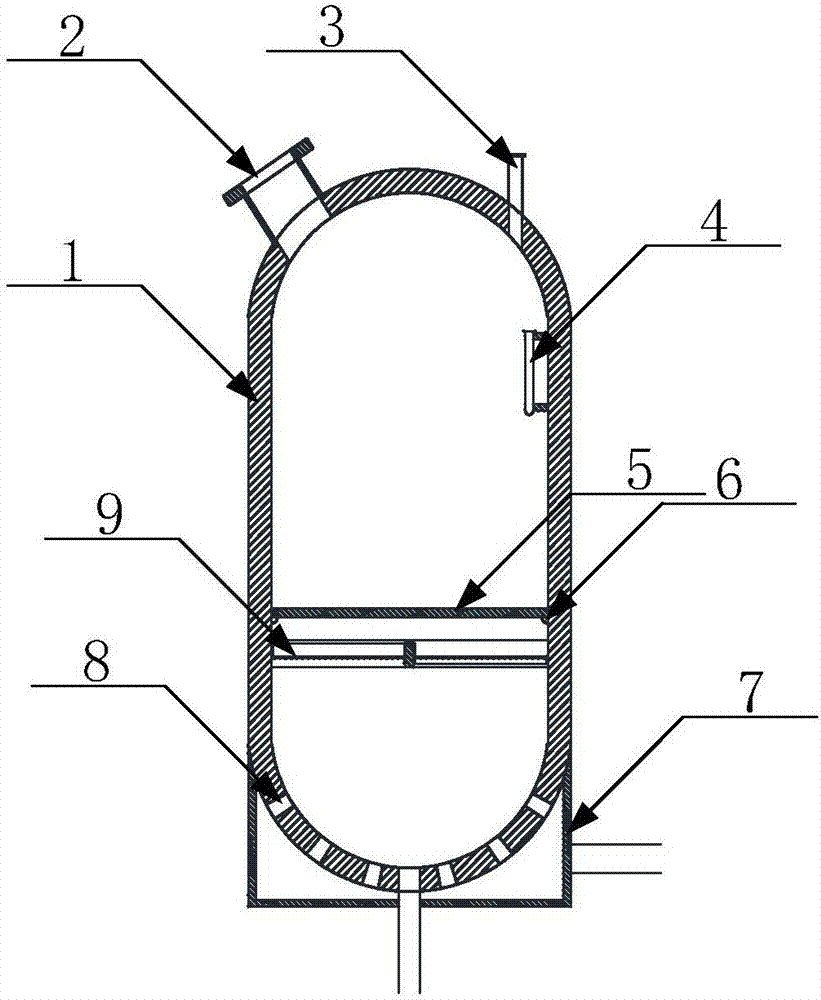
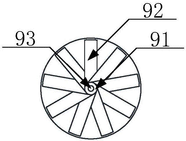
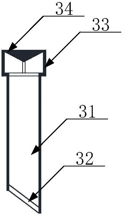
[0030] like figure 1 As shown, a self-removing pneumatic stirring device includes a tank body 1, a feed inlet 2 and an exhaust structure 3 arranged on the upper end of the pipe body 1, and an impurity collection pipe 4 arranged on the inner wall of the tank body 1, surrounded by a pipe The support ring 6 on the inner wall of the body 1 and located below the impurity collection pipe 4, the protective net 5 fixed on the support ring 6, the air passage chamber 7 arranged on the lower side of the tank body 1, penetrates the tank body 1 and connects the tank body 1 with the The air intake structure 8 connected to the air chamber 7 and the rotary fan 9 arranged on the lower side of the protective net 5 .

[0031] A liquid discharge port is provided at the center of the bottom of the tank body 1 , and a liquid inlet port is provided at any position on the tank body 1 ; a gas inlet connected to the outside is also provided on the gas chamber 7 .

[0032] The bottom of the tank body i...


PUM


Abstract

The invention discloses an automatic impurity removal pneumatic stirring device. The automatic impurity removal pneumatic stirring device comprises a tank body, a feeding hole, an exhaust structure, an impurity collecting pipe, a support ring, a protection screen, an air flow cavity, an air inlet structure and a rotating fan, wherein the feeding hole and the exhaust structure are formed in and arranged at the upper end of the tank body; the impurity collecting pipe is arranged on the inner wall of the tank body; the support ring is arranged around the inner wall of the tank body and is positioned below the impurity collection tube; the protection screen is fixed to the support ring; the air flow cavity is formed in the lower side of the tank body; the air inlet structure passes through thetank body, and connects the tank body with the air flow cavity; the rotating fan is arranged on the lower side of the protection screen. According to the automatic impurity removal pneumatic stirringdevice, a novel stirring machine design idea is provided, so that the difficulty in cleaning the inside of a stirring machine is lowered, a stirring stick is removed, and the internal structure of the stirring machine is further simplified.

Description

technical field [0001] The invention relates to the field of mechanical equipment, in particular to a self-cleaning pneumatic stirring device. Background technique [0002] Mixers are often used for mixing materials and are a kind of equipment commonly used in production. When mixing soluble solids and liquids, insoluble impurities are often deposited on the bottom of the tank or attached to the stirring rod, which needs to be cleaned frequently, which consumes a lot of labor. At the same time, the stirring rod needs to be disassembled, replaced and cleaned regularly , Time-consuming and labor-intensive, increasing the burden on the enterprise. Contents of the invention [0003] The purpose of the present invention is to overcome the above problems, provide a self-cleaning pneumatic stirring device, provide a new design idea of ​​the mixer, reduce the difficulty of cleaning inside the mixer, eliminate the stirring rod, and further reduce the internal structure of the mixe...

Claims


Application Information

Patent Timeline
Patent Type & Authority Applications(China)
IPC IPC(8): B01F13/02B01F15/00B01F1/00B01F33/40
CPCB01F21/503B01F21/00B01F33/402B01F33/406B01F35/187
Inventor 王前明
Owner 四川新驱科为科技有限公司
Why Eureka
Try Eureka