
Press plate and outgoing line matching structure for transformer and outgoing line method of press plate and outgoing line matching structure

A matching structure and transformer technology, applied in transformer/inductor parts, inductance/transformer/magnet manufacturing, electrical components, etc., can solve the problems of complex structure of transformer pressure plate and outgoing line, difficult to ensure installation size, etc., and achieve simple structure Ingenious, reduced labor costs, and convenient operation

Pending Publication Date: 2018-04-03
TBEA SHENYANG TRANSFORMER GRP CO LTD
View PDF0 Cites 2 Cited by
  • Summary
  • Abstract
  • Description
  • Claims
  • Application Information

AI Technical Summary

Problems solved by technology

[0003] Aiming at the shortcomings of the prior art, such as the complex structure of the transformer pressure plate and the outgoing line, it is difficult to ensure the installation size of the design theory, the problem to be solved by the present invention is to provide a transformer pressure plate and outgoing line matching structure and its outgoing line that are easy to operate and ensure heat dissipation efficiency. method

Method used


Image

  • Press plate and outgoing line matching structure for transformer and outgoing line method of press plate and outgoing line matching structure
  • Press plate and outgoing line matching structure for transformer and outgoing line method of press plate and outgoing line matching structure
  • Press plate and outgoing line matching structure for transformer and outgoing line method of press plate and outgoing line matching structure

Examples


Embodiment Construction

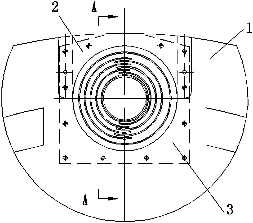
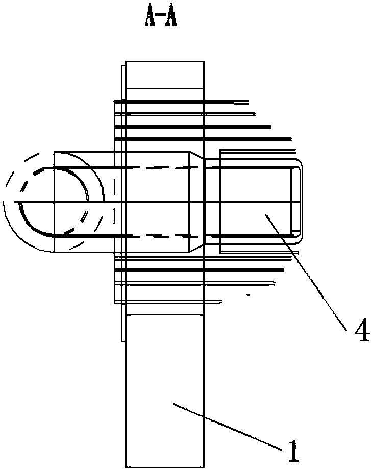
[0028] The present invention will be further elaborated below in conjunction with the accompanying drawings of the description.

[0029] Such as Figure 1A , 1B As shown, the transformer of the present invention has a matching structure between the pressure plate and the outgoing line, which has a pressure plate and an oil seal plate 3. The pressure plate includes two parts: the pressure plate body 1 and the cushion block 2. Plate 3 is installed on the lower part of the pressing plate.

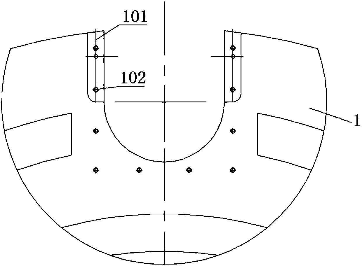
[0030] Such as figure 2 As shown, one side of the platen body 1 is provided with an open notch, the edge of the notch is the installation side, and the notch is in an inverted ladder shape in the thickness direction; in this embodiment, the notch adopts a U-shaped mouth, and the spacer 2 passes through Cardboard pins are installed on both sides of the U-shaped mouth.

[0031] Such as Figure 3A , 3B As shown, the spacer 2 has an opening abutting with the notch of the pressure plate body ...


PUM


Abstract

The invention relates to a press plate and outgoing line matching structure for a transformer and an outgoing line method of the press plate and outgoing line matching structure. The press plate and outgoing line matching structure is provided with a press plate and an oil sealing plate, wherein the press plate comprises a press plate body and a cushion block, the press plate body and the cushionblock are connected in a sliding way and in a step abutting mode, and the oil sealing plate is arranged at a lower part of the press plate. The method comprises the steps of separating the press platebody from the cushion block in a drawer mode, and allowing the press plate to expose out of an opened groove; installing an outlet each-layer angle ring and an insulation piece at the groove; inserting the cushion block into the groove for installation after the outlet each-layer angle ring and the insulation piece are completed, and fixing the cushion block by a paperboard pin; installing and fixing the oil sealing plate at a corresponding position of the lower part of the press plate by employing an insulation screw rod and a nut, so that the integral structure is completed. An epitaxial part of an hole of the press plate is separated in a drawer mode, the operation space of the outlet installation angle ring and the insulation piece is also ensured on the premise that the installationsize requirement of a design theory is ensured, operation is facilitated, and meanwhile, the cooling efficiency of a strong oil guide structure of a product is ensured.

Description

technical field [0001] The invention relates to a manufacturing technology of a transformer, in particular to a matching structure of a pressure plate and an outgoing line for a transformer and an outgoing line method thereof. Background technique [0002] With the rapid development of UHV transmission projects, the voltage level and transmission capacity of transmission lines continue to increase, and the demand for high-voltage and large-capacity power transformer products is also increasing year by year. The terminal insulation level determines the complex terminal outlet structure of the transformer, that is, the oil-paper partition type outlet method composed of multi-layer corner rings and stays. In the actual assembly operation of the coil set, the conventional pressing plate is a circular plate with outlet holes, which are closed in a circular shape. After the lower pressure plate is installed first, the complex outgoing line structure at the lower end of the transf...

Claims


Application Information

Patent Timeline
Patent Type & Authority Applications(China)
IPC IPC(8): H01F27/04H01F41/00
CPCH01F27/04H01F41/00
Inventor 宋承志李哲
Owner TBEA SHENYANG TRANSFORMER GRP CO LTD
Learn More