
Central beam assembly applicable to railway wagon having large weight-concentrating capability

A technology for railway wagons and capacity, which is applied to railway car body components, chassis, transportation and packaging, etc., and can solve the problems of small space for side beams, great impact on train inspection work efficiency, and inconvenience for train inspectors to enter under the car for inspection, etc. , to achieve the effects of improving the stress condition, uniform stress, improving quality and life

Active Publication Date: 2014-02-19
CRRC QIQIHAR ROLLING CO LTD
View PDF5 Cites 0 Cited by
  • Summary
  • Abstract
  • Description
  • Claims
  • Application Information

AI Technical Summary

Problems solved by technology

[0005] Limited by the strength and stiffness of the center sill, existing trucks can only increase the overall rigidity of the car body by increasing the section of the side sill accordingly. Often the side sill is as high as the section of the center sill, which causes the problem that the space between the lower part of the side sill and the limit is too large. Small size, it is not convenient for train inspectors to enter under the train for inspection, which has a great impact on the efficiency of train inspection work, and has become a typical problem for large-scale railway freight cars

Method used


Image

  • Central beam assembly applicable to railway wagon having large weight-concentrating capability
  • Central beam assembly applicable to railway wagon having large weight-concentrating capability
  • Central beam assembly applicable to railway wagon having large weight-concentrating capability

Examples


Embodiment Construction

[0027] The present invention will be described in detail below in conjunction with the accompanying drawings and embodiments.

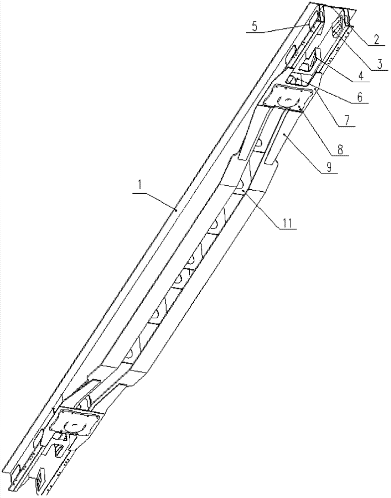
[0028] Such as Figure 1~3 As shown, the present invention includes: a fish-bellied center beam 1 made of two H-shaped steels, an inner draw beam 2 positioned in the webs at both ends of the center beam, a front slave plate seat 3 and a rear plate seat fixed on the inner draw beam. From the board seat 4 and the reinforcement beam 5 from the board seat hole, the pillow middle partition 6 and the center plate backing plate 7 located in the center beam web behind the inner traction beam 2, the upper center plate 8 and the pillow installed on the center plate backing plate Rear center plate reinforcement plate 9, and pillow center connecting plate 10 located between the upper wing edges of the center sill, center sill partition 11 located in the middle web of the center sill, upper cover plate 12 at the top of the center sill, and lower cover plate 13 at ...


PUM


Abstract

The invention discloses a central beam assembly applicable to a railway wagon having a large weight-concentrating capability. The central beam assembly is characterized by comprising two abdominal central beams made of H-type steel, wherein an inner interval of two web plates of the central beams is 400-600mm; the web plates are connected through a central beam separating plate; the height of an abdominal part of each of the central beams is above 700mm and is gradually reduced toward two ends; inner towing beams shaped like a Chinese character 'ji' are nested between the web plates at two ends of the central beams; and the inner interval of the inner towing beams is 350mm. According to the invention, the two abdominal central beams made of H-type steel and the nested hat-shaped inner towing beams are installed and welded into a nested double-web plate central beam structure, the interval of web plates of the two abdominal central beams can be increased to 400-600mm, the effect of using large-size structural steel with wider winged edges as the central beams is realized, and an operation space for welding the central beam separating plate is ensured; and through installing and welding of large-size structural steel central beams, the central beams can achieve higher stiffness and strength and are applicable to the railway wagon having a 80t or 90t weight-concentrating capability. The nested hat-shaped inner towing beams are used for realizing mounting and barffing of a 350mm wagon coupler buffering device.

Description

technical field [0001] The invention relates to a middle girder structure for railway freight cars, which is suitable for car bodies with large load-collecting capacity, and can increase the load-collecting capacity of the vehicle from 70t to 80t or 90t. Background technique [0002] With the leap-forward development of "speed, density, and weight", railway freight cars have achieved technical upgrades from 60t to 70t, and are developing towards 80t and even 90t. The performance requirements of the vehicles are getting higher and higher. Moreover, in order to give full play to the advantages of long railway transportation distance and low energy consumption to promote the progress of the logistics industry, the loading range of railway freight cars is also expanding, and high-density goods such as generator rotors and large steel coils continue to enter railway transportation This puts forward higher requirements for the weight-collecting capacity of railway freight cars. Th...

Claims


Application Information

Patent Timeline
Patent Type & Authority Patents(China)
IPC IPC(8): B61F1/02
Inventor 孙晓云廖小平徐海涛关雪梅王武建兰叶
Owner CRRC QIQIHAR ROLLING CO LTD
Learn More