
Axial elastic component for synchronizer system and synchronizer system

A technology of elastic components and synchronizers, which is applied in the direction of clutches, mechanical drive clutches, mechanical equipment, etc., and can solve the problems of secondary impact of shifting, insufficient comfort of shifting, and secondary peaks of shifting force, etc.

Active Publication Date: 2021-07-23
SCHAEFFLER TECH AG & CO KG
View PDF5 Cites 0 Cited by
  • Summary
  • Abstract
  • Description
  • Claims
  • Application Information

AI Technical Summary

Problems solved by technology

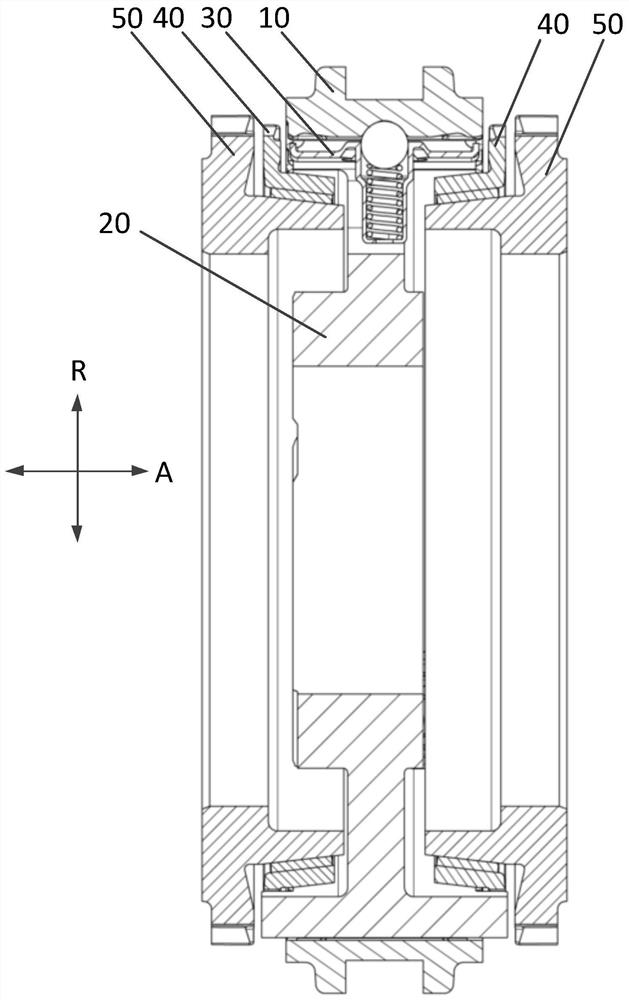
But, because in the synchronization process of the synchronizer system of the prior art mentioned above, when the friction pair of the synchronous ring 40 and the ring gear 50 exists in the situation that the dialing ring stage and the free travel stage are not released, like this, if the meshing stage starts It may cause a secondary impact on the gear shift, causing the gear shift force to appear a secondary peak during the entire gear shift process, resulting in insufficient shift comfort

Method used


Image

  • Axial elastic component for synchronizer system and synchronizer system
  • Axial elastic component for synchronizer system and synchronizer system
  • Axial elastic component for synchronizer system and synchronizer system

Examples


Embodiment Construction

[0039] Specific embodiments of the present invention will be described below with reference to the accompanying drawings. In the drawings, the mark "R" represents the radial direction of the synchronizer system, the mark "A" represents the direction in which the central axis of the synchronizer system extends, and the mark "C" represents the circumferential direction of the axial elastic component (thrust bearing).

[0040] (Overall structure of the synchronizer system according to the present invention)

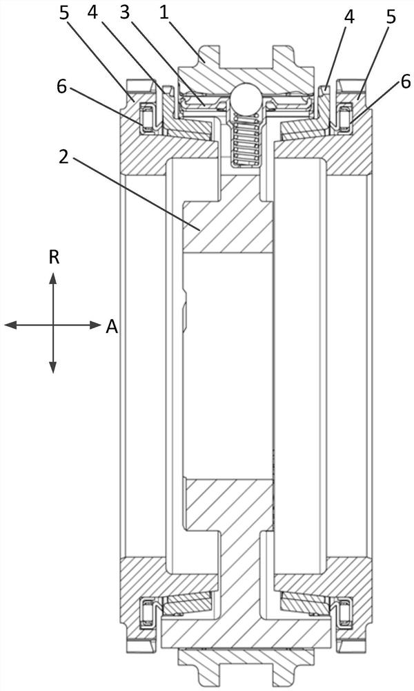
[0041] refer to figure 2 The overall structure of the synchronizer system according to the present invention will be described. Such as figure 2 As shown, the synchronizer system according to the present invention includes a gear sleeve 1 , a gear hub 2 , a synchronizer slider 3 , a synchronizer ring 4 , a ring gear 5 and an axial elastic component 6 .

[0042] According to the overall structure of the synchronizer system of the present invention and figure 1 The overa...


PUM


Abstract

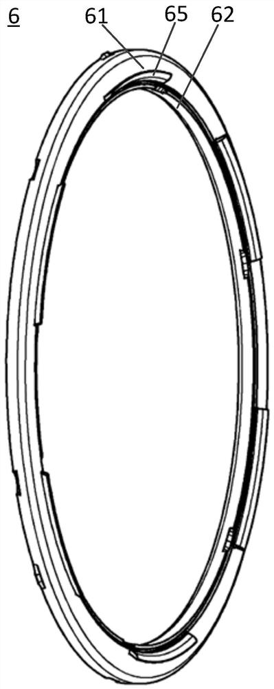
The invention relates to the field of synchronizers, in particular to an axial elastic component for a synchronizer system and a synchronizer system. The axial elastic component for a synchronizer system according to the present invention includes: a thrust bearing; and an elastic portion, which is disposed on one of the outer ring or the inner ring of the thrust bearing and extends away from the thrust bearing. When the elastic portion is elastically deformed, the elastic portion can generate an axial elastic force. In addition, the invention also provides a synchronizer system using the axial elastic component. In this way, the synchronous system according to the present invention facilitates the disengagement of the synchronous ring from the ring gear by providing additional axial force, thereby reducing the probability of secondary impact of the shifting force during the entire shifting process and improving shifting comfort.

Description

technical field [0001] The invention relates to the field of synchronizers, in particular to an axial elastic component for a synchronizer system and a synchronizer system using the axial elastic component. Background technique [0002] The synchronizer is one of the key components in the transmission, especially the automobile transmission, and the performance of the synchronizer directly determines the shifting performance of the transmission. [0003] figure 1 A schematic cross-sectional view of a prior art synchronizer system (lock ring inertial synchronizer system) is shown in . Such as figure 1 As shown, the synchronizer system includes a gear sleeve 10 , a gear hub 20 , a synchronizer slider 30 , a synchronizer ring 40 and a ring gear 50 . The gear sleeve 10 is coupled to the gear hub 20 from the outer side in the radial direction R and can slide in the axial direction A due to the action of a shift fork (not shown). Spline connection is adopted between gear hub 2...

Claims


Application Information

Patent Timeline
Patent Type & Authority Patents(China)
IPC IPC(8): F16D23/02
CPCF16D23/02F16D2023/065
Inventor 秦芳费磊周怡青张文鑫杨春莹吴卫国
Owner SCHAEFFLER TECH AG & CO KG
Learn More