


Quick Research
Generate reliable direction feasibility study reports for your R&D in just a few steps.

Technical Q&A
Discover and master advanced knowledge NOW. Basics, ideas, possibilities, all at once.

Find Solutions
As an expert in R&D theories, this can generate solutions to your technical problems instantly.

Evaluate Feasibility
Analyze your overall solution with one click, know your potential R&D risks in advance.

Monitor Landscape
Get weekly tech updates, stay abreast of the latest tech innovations and key insights.
Design method and structure of bearing jig for checking large-size plate card
A design method and large-scale technology, applied in measurement devices, material analysis by optical means, instruments, etc., can solve problems such as bad outflow, electrostatic damage, collisions, etc., to increase the output per unit time and improve the detection rate. , the effect of reducing the accumulation of fatigue
- Summary
- Abstract
- Description
- Claims
- Application Information
AI Technical Summary
Problems solved by technology
Method used
Image

Examples
Embodiment 1
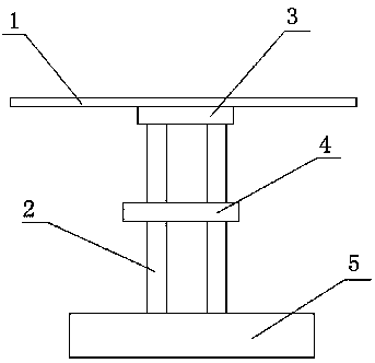
[0025] A method for designing a load-carrying jig for inspection of large-sized boards, said method fixes a board to be inspected by setting a board carrier 1, and sets the board carrier 1 on the board support column 2 On the workbench: by setting the rotating device, the board carrier 1 can be rotated in the horizontal direction, which is convenient for inspectors to adjust the viewing angle during inspection.
[0026] The method content also includes:
[0027] The carrier board support column 2 is provided with a steering device 4, which can make the carrier board support column 2 adjust the angle in the vertical direction. By setting the steering device 4 in the vertical direction, the position and angle of the board card carrier board 1 can be further adjusted to facilitate Inspectors observe.
[0028] The method also includes:
[0029] The carrier support column 2 is set on the worktable through the jig base 5 . By arranging a carrier base 5, on the one hand, the jig c...
Embodiment 2
[0031] Such as figure 1 As shown, a load-bearing jig structure for large-scale board inspection, the structure of the jig includes a board carrier 1, a carrier support column 2, and a carrier rotating disk 3, wherein the carrier rotating disk 3 is set Between the board carrier 1 and the carrier support column 2 , the board carrier 1 can be rotated by the carrier rotating disk 3 .
[0032] The support column 2 of the carrier board is divided into two parts, and a steering device 4 is arranged between the two parts. The purpose of designing the steering device 4 is to adjust the horizontal angle of the carrier board when the carrier board faces the operator. Perspective change.
[0033] The structure of the jig also includes a carrier base 5 , and the board carrier 1 is arranged on the carrier base 5 through the carrier support column 2 .
[0034] The steering device 4 provided between the two parts of the carrier support column 2 is a rotating shaft with damping, which can fi...
PUM
 Abstract
Description
Claims
Application Information
 - R&D Engineer
- R&D Manager
- IP Professional
- Industry Leading Data Capabilities
- Powerful AI technology
- Patent DNA Extraction
Browse by: Latest US Patents, China's latest patents, Technical Efficacy Thesaurus, Application Domain, Technology Topic, Popular Technical Reports.
© 2024 PatSnap. All rights reserved.Legal|Privacy policy|Modern Slavery Act Transparency Statement|Sitemap|About US| Contact US: help@patsnap.com