Shirt press machine

a press machine and shirt technology, applied in the field of shirt press machines, can solve the problems of fatigue accumulation of workers, inability to perform repetitive work, and consumption of time required for the movement of left to right, and achieve the effect of easy and quick pressing

Inactive Publication Date: 2009-05-12
KIM BYUNG HAK
View PDF5 Cites 2 Cited by
  • Summary
  • Abstract
  • Description
  • Claims
  • Application Information

AI Technical Summary

Benefits of technology

[0007]Accordingly, the present invention has been made in an effort to solve the above problems occurring in the prior art, and it is an object of the present invention to provide a shirt press machine by which an operator can easily and readily press a body part, a left and right sleeves of a shirt after fixing them on the machine while standing near the middle portion of the machine without moving from a position to another position.
[0008]Another object of the invention is to provide a shirt press machine by which an operator can operate while standing near the middle portion of the machine, thereby reducing fatigue accumulation of the operator.
[0009]Still, another object of the invention is to provide a shirt press machine by which an operator can rapidly operate while standing near the middle portion of the machine by reducing the time required for her or his movement of left to right, thereby achieving a more effective operation in a large-sized laundry shop.
[0011]In accordance with the present invention, when a shirt to be pressed is transported to an operator, the operator can hang the shirt on the machine while standing near the middle of the machine without her or his movement of left to right so as to hang the body part and left-right sleeves of the shirt on the machine, and then the shirt can be pressed by means of a simple operation means such as a button.

Problems solved by technology

During such a pressing process, since the worker has to perform many actions while repeating his or her movement of left to right, the repetitive work is inevitably performed and the time required for the movement of left to right is consumed accordingly.
In such a conventional shirt press machine, fatigue accumulation of the worker is induced and much working time is spent.

Method used


Image

  • Shirt press machine
  • Shirt press machine
  • Shirt press machine

Examples


Embodiment Construction

[0024]Hereinafter, the transparent ornament of the present invention will be described in detail with reference to the appended drawings.

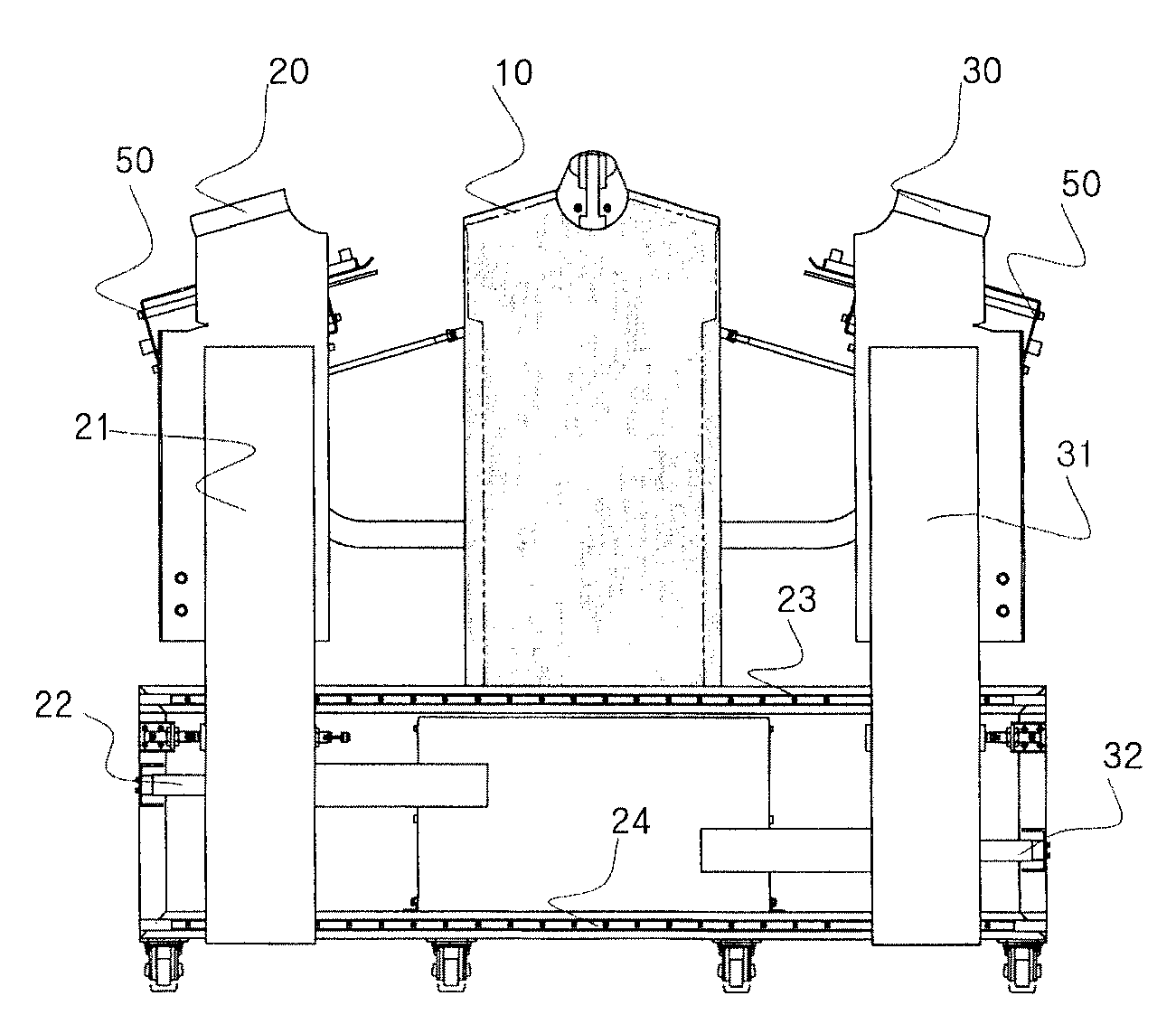
[0025]FIG. 1 is a front view of a shirt press machine according to an embodiment of the present invention.

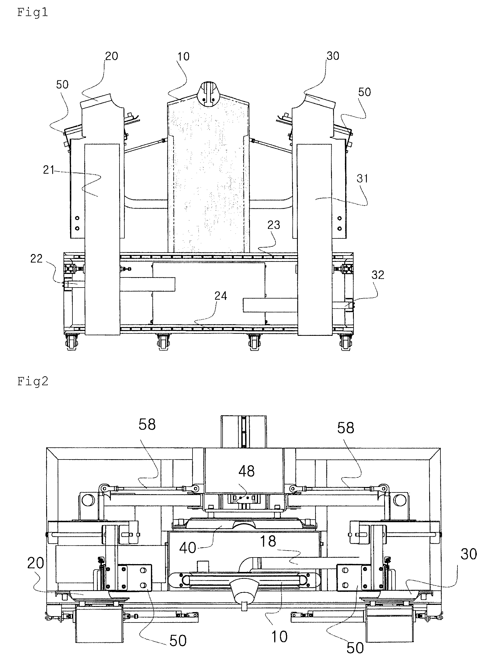
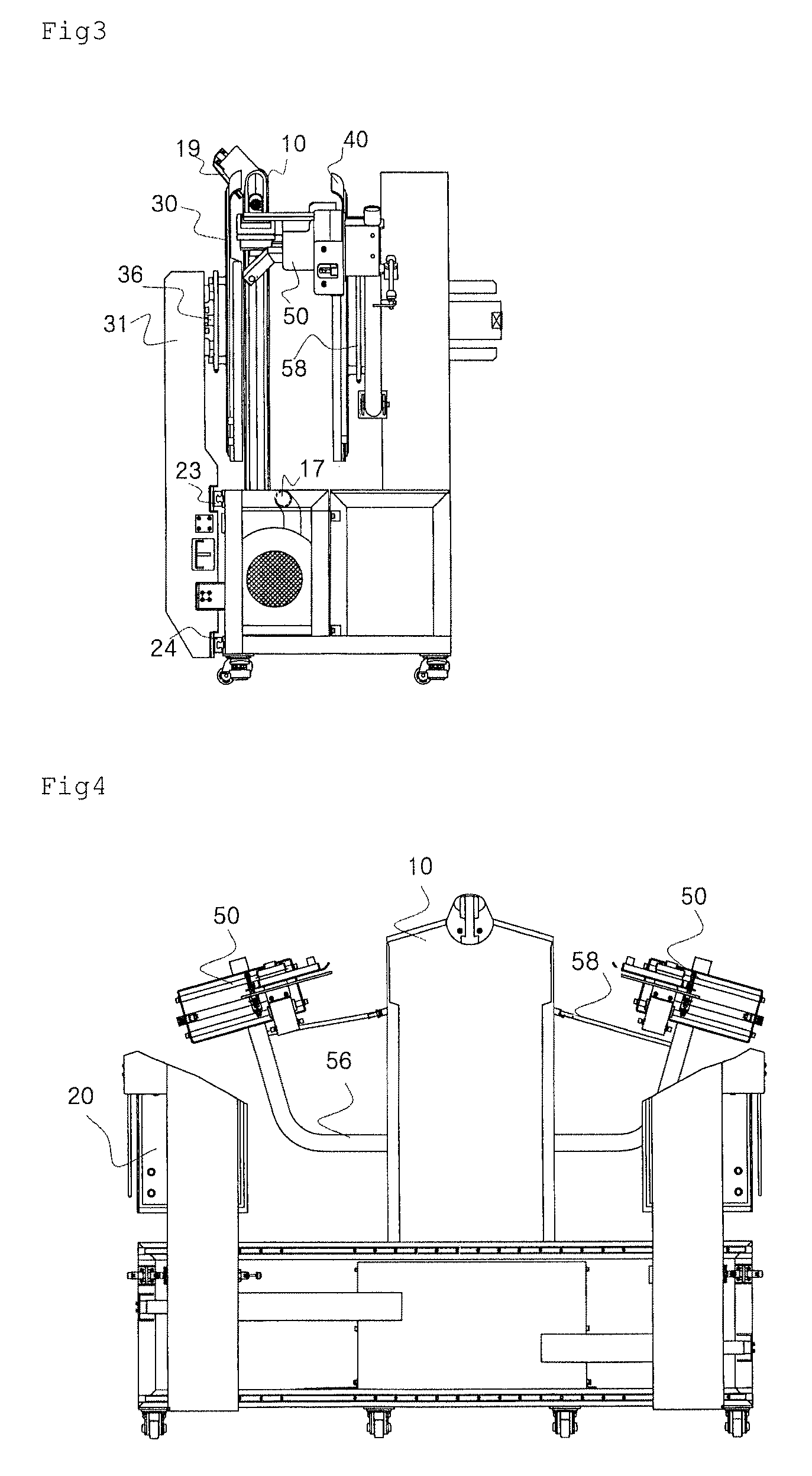
[0026]As shown in FIG. 1, the shirt press machine according to an embodiment of the present invention comprises: a front left side press 20 for pressing a front left side part of a shirt which is hung on a human body model 10; a front right side press 30 for pressing a front right side part of the shirt; and a rear press 40 for pressing a rear part of the shirt, wherein the front left and right side presses 20 and 30 approach the front left and right side parts of the shirt hung on the human body model, respectively, so as to press the front left and right side parts of the shirt, and wherein the rear press 40 approaches the rear part of the shirt so as to press the rear part of the shirt.

[0027]In accordance with the shirt press machine accordi...


PUM


Abstract

The present invention relates to a shirt press machine which comprises a front left side press; a front right side press; and a rear press for pressing a rear part of the shirt, wherein the front left and right side presses approach the front left and right side parts of the shirt, respectively, so as to press them, and wherein the rear press approaches the rear part of the shirt so as to press it. The shirt press machine further comprises a pair of support arms for supportingly spreading out, the sleeves of the shirt, so that a high temperature and pressure hot air is applied to the sleeves of the shirt which are supportingly spread out obliquely downwardly to the left and right by the pair of support arms, thereby allowing the sleeves of the shirt to be ironed.

Description

BACKGROUND OF THE INVENTION[0001]1. Field of the Invention[0002]The present invention relates to a shirt press machine, and more particular, to a shirt press machine in which a pair of presses are separately mounted on the front left and right sides of the shirt press machine so as to allow a worker to easily and readily work while standing near the middle portion of the shirt press machine.[0003]2. Background of the Related Art[0004]In general, a conventional shirt press machine has a single press mounted at the center of the front side thereof. Thus, a worker needs to do much labor so as to press a shirt or apply a hot air to the shirt, that is, the worker has to move to the left when fixing and ironing the left sleeve of the shirt, and, move to the right when fixing and ironing the right sleeve. In other words, a pressing process of the conventional shirt press machine is performed such that left and right sleeves of the shirt are fixed on the press machine, are pulled to the lef...

Claims


Application Information

Patent Timeline
Patent Type & Authority Patents(United States)
IPC IPC(8): D06F71/20D06F59/02
CPCD06F71/20
Inventor KIM, BYUNG HAK
Owner KIM BYUNG HAK
Why Eureka
Try Eureka