
Heat regeneration device utilizing compressed air waste heat

A technology for compressing air and heat devices, applied in steam engine devices, machines/engines, mechanical equipment, etc., can solve the problems of temperature drop, efficiency drop, limited total heat of compression, etc., to avoid pressure loss, increase intake temperature, simple structure

Inactive Publication Date: 2018-03-30
TSINGHUA UNIV
View PDF9 Cites 0 Cited by
  • Summary
  • Abstract
  • Description
  • Claims
  • Application Information

AI Technical Summary

Problems solved by technology

However, due to the throttling refrigeration effect of the compressed gas during the throttling expansion process, the temperature drops sharply. The temperature of the compressed gas after throttling is generally -20°C to -15°C. The amount of heat is limited, and part of the heat is used to make up for throttling heat loss, the heat used to improve the actual working capacity will be reduced, and the efficiency of the system will be greatly reduced

Method used


Image

  • Heat regeneration device utilizing compressed air waste heat
  • Heat regeneration device utilizing compressed air waste heat
  • Heat regeneration device utilizing compressed air waste heat

Examples


Embodiment Construction

[0021] In order to make the purpose, technical solutions and advantages of the invention clearer, the technical solutions in the invention will be clearly described below in conjunction with the accompanying drawings in the invention. Obviously, the described embodiments are part of the embodiments of the invention, not all of them. Example. Based on the embodiments of the invention, all other embodiments obtained by persons of ordinary skill in the art without making creative efforts belong to the protection scope of the invention.

[0022] In the description of the present invention, unless otherwise specified, the orientations or positional relationships indicated by the terms "top", "bottom" and the like are based on the orientations or positional relationships shown in the drawings, and are only for the convenience of describing the present invention and simplifying the description. It is not intended to indicate or imply that the system or element referred to must have a...


PUM


Abstract

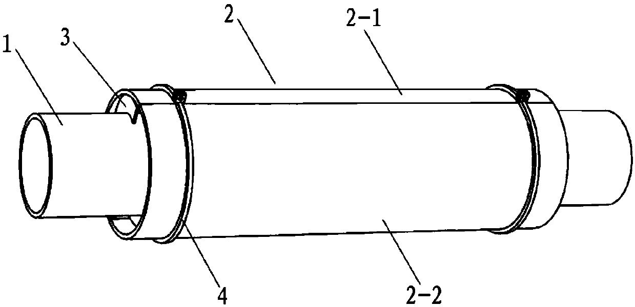
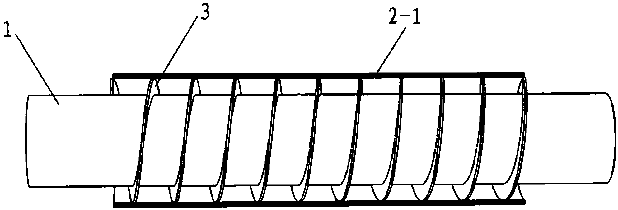
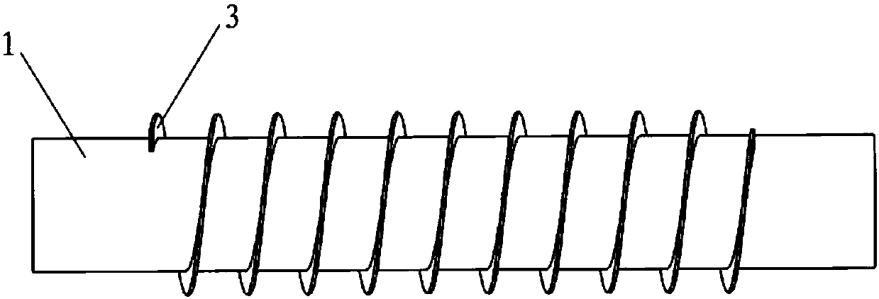
The invention relates to the technical field of compressed air energy storage, and provides a heat recovery device utilizing the residual temperature of compressed air. The device includes a sealing tube, an end cover and a spiral fin. The sealing tube is sleeved on the compressed air delivery tube used to communicate with the throttling device and the turbine. The spiral fin is arranged between the compressed air delivery tube and the sealing tube. Between the outer wall of the compressed air delivery pipe and the inner wall of the sealing pipe, a spiral air channel is formed. One end cover of the sealing pipe is provided with an end cover, and the end cover is provided with an air intake pipe and a compressed air delivery pipe. One end of the inlet pipe communicates with the inlet of the spiral air channel, and the other end is used to communicate with the exhaust port of the turbine. The invention not only realizes the effective utilization of the residual temperature of the exhaust gas of the turbine, but also improves the inlet temperature and system efficiency of the turbine. In addition, because the present invention does not change the flow channel inside the compressed air delivery pipe, it avoids additional pressure loss during compressed air delivery.

Description

technical field [0001] The invention relates to the technical field of compressed air energy storage, in particular to a heat recovery device utilizing residual temperature of compressed air. Background technique [0002] With the development of the economy, people's demand for electric energy is also increasing, and the storage of electric energy is of great significance to the optimization of energy structure and the regulation of power grid operation. The compressed air energy storage system is a new type of energy storage technology. The system generally includes an air compressor, a gas storage device, a turbine and a throttling device. The compressed air in the gas storage device needs to be transported to the turbine. [0003] Among them, the traditional compressed air energy storage system also includes a burner. After the high-pressure air released by the gas storage device is throttled by the throttling device, it can only be used for expansion after it is mixed w...

Claims


Application Information

Patent Timeline
Patent Type & Authority Applications(China)
IPC IPC(8): F01K27/00
CPCF01K27/00
Inventor 梅生伟薛小代陈来军卢强
Owner TSINGHUA UNIV
Learn More