Flow guide tunnel by utilizing permanent plug head section joint gate opening and plugging arrangement and method

A technology of diversion tunnels and plugs, which is applied in water conservancy projects, hydroelectric power stations, hydroelectric power generation, etc., can solve the high risk of water blocking safety at the entrance of the diversion tunnel, increase the risk of the import structure during the blocking period, and the geology of the project import. Complex conditions and other problems, to achieve the effect of eliminating the safety risk of water retention, optimizing the arrangement and method of plugging, and improving the safety of water retention

Pending Publication Date: 2018-03-30
CHANGJIANG SURVEY PLANNING DESIGN & RES
View PDF3 Cites 1 Cited by
  • Summary
  • Abstract
  • Description
  • Claims
  • Application Information

AI Technical Summary

Problems solved by technology

[0005] (2) For projects with complex geological conditions at the entrance of the diversion tunnel, the diversion tunnel is blocked and operated at a high water head, and there is a certain safety risk in the structure of the diversion tunnel entrance
The diversion tunnel is a temporary project, and the geological conditions at the entrance of some projects are complex. When the water head is running, the safety risk of the water retaining structure at the entrance of the diversion tunnel is high
[0006] (3) For projects with multiple diversion tunnels, in order to reduce the amount of excavation and support work at the entrance of the diversion tunnel, the multiple diversion tunnels arranged on the same bank are generally arranged at staggered distances. For projects with complex geological conditions at the entrance, The staggered layout will lead to the problem of partial pier bias in the entrance section of the diversion tunnel during the closure period of the lower gate, which will increase the structural risk of the entrance during the closure period

Method used


Image

  • Flow guide tunnel by utilizing permanent plug head section joint gate opening and plugging arrangement and method
  • Flow guide tunnel by utilizing permanent plug head section joint gate opening and plugging arrangement and method
  • Flow guide tunnel by utilizing permanent plug head section joint gate opening and plugging arrangement and method

Examples


Embodiment Construction

[0032] The implementation of the present invention will be described in detail below in conjunction with the accompanying drawings, but they do not constitute a limitation to the present invention, they are only examples, and at the same time, the advantages of the present invention will become clearer and easier to understand.

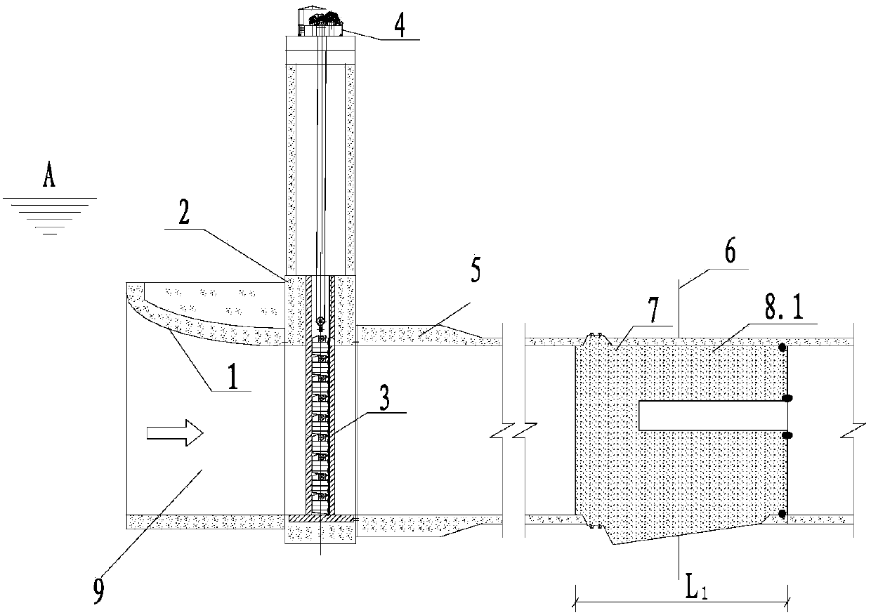
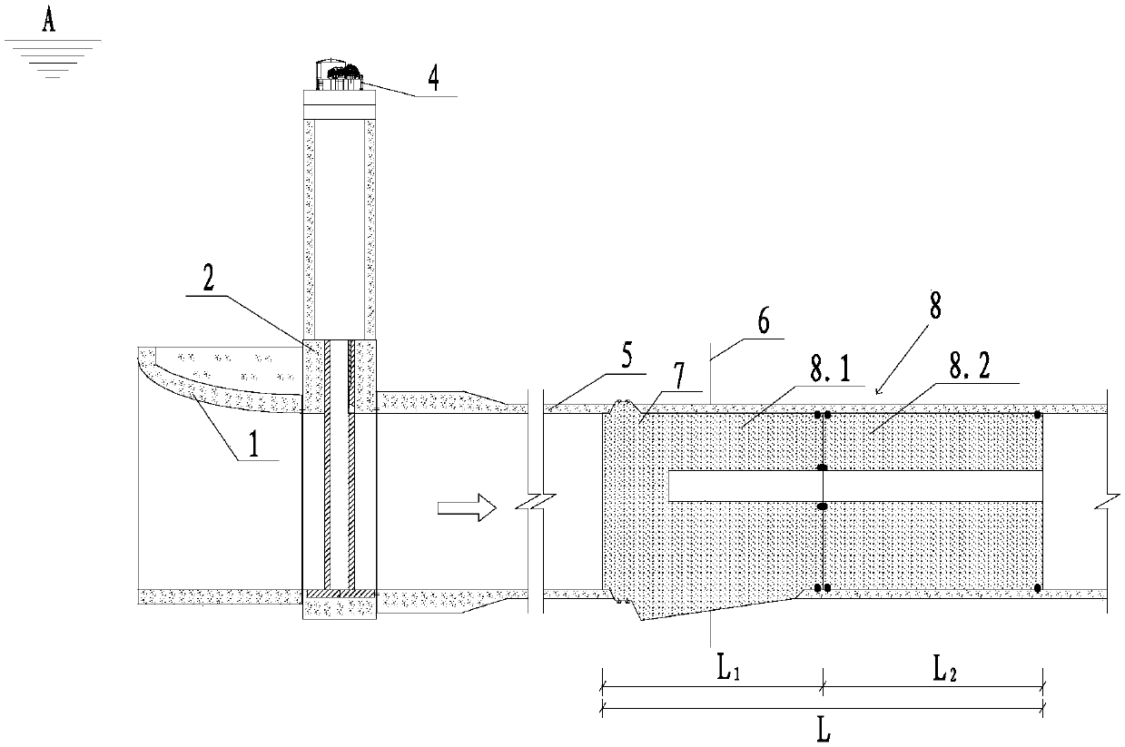
[0033] refer to Figure 1-2 Shown: the diversion tunnel utilizes the first section of the permanent plug joint gate to be closed and arranged. It includes a plurality of diversion tunnels 9 to form a diversion tunnel group, and the diversion tunnel group includes two batches of the diversion tunnels respectively The diversion tunnel 9, the diversion tunnel 9 of the first batch of lower gates includes the diversion tunnel entrance section 1 and the diversion tunnel body 1.1; the diversion tunnel entrance section 1 is provided with a low water head blocking gate 3. A water inlet tower 2 is installed at the entrance section 1 of the diversion tunnel, and...


PUM


Abstract

The invention discloses a flow guide tunnel by utilizing permanent plug head section joint gate opening and plugging arrangement and a method. The flow guide tunnel by utilizing permanent plug head section joint gate opening and plugging arrangement comprises a diversion tunnel group which is formed by a plurality of flow guide tunnels (9), and the diversion tunnel group is divided into two batches for opening a gate. The first batch of flow guide tunnels (9) for opening the gate comprise diversion tunnel inlet sections (1) and diversion tunnel bodies (1.1), and lower water head blocking gatesare arranged at the diversion tunnel inlet sections (1). The flow guiding tunnel inlet sections (1) are provided with water inlet towers (2), the top of the water inlet towers (2) are provided with small-capacity openings and closing machines (4). Permanent plugs (8) consist of permanent plug upstream sections (8.1) and downstream sections (8.2), and the permanent plug upstream sections (8.1) andthe downstream sections (8.2) are arranged in a combined mode. The defects that a water retaining head of a diversion tunnel blocking gate is high and the engineering investment is large in the priorart are overcome. The method has the advantage of innovation of an existing diversion tunnel opening and plugging technology.

Description

technical field [0001] The invention relates to the technical field of water conservancy and hydropower, and more specifically relates to the arrangement and method for sealing a diversion tunnel by using a first section of a permanent plug combined with a lower gate of a gate. Background technique [0002] In the construction of hydropower projects in mountainous rivers, the construction diversion scheme of cofferdams blocking the riverbed at one time and diversion tunnels for diversion is often used during the construction period. For rivers with large runoff, two or more diversion tunnels are often arranged to form a group of diversion tunnels. After the diversion tunnel group completes the task of diversion and discharge, it must be blocked by lower gates to meet the requirements of water storage and power generation. After the diversion tunnel group is lowered, in order to meet the requirements of water discharge during the construction period, the diversion bottom hole...

Claims


Application Information

Patent Timeline
Patent Type & Authority Applications(China)
IPC IPC(8): E02B9/06
CPCE02B9/06Y02E10/20
Inventor 翁永红徐唐锦李蘅饶志文漆祖芳范五一胡清义郭鸿俊
Owner CHANGJIANG SURVEY PLANNING DESIGN & RES
Why Eureka
Try Eureka