Eureka AIR delivers breakthrough ideas for toughest innovation challenges, trusted by R&D personnel around the world.

Charging system control method used for charging new-energy automobile

A technology of new energy vehicles and charging systems, applied in the field of charging devices, can solve problems such as parking forgetting to charge, manual charging, automatic movement of charging lines, etc., and achieve fast and stable charging, automation, and convenience for practical cars

Inactive Publication Date: 2018-03-30
朱森
View PDF0 Cites 0 Cited by
  • Summary
  • Abstract
  • Description
  • Claims
  • Application Information

AI Technical Summary

Problems solved by technology

[0004] The purpose of the present invention is to provide a charging system control method for new energy vehicle charging in view of the above existing problems, which solves the problem of manual charging, the efficiency of automatic charging, and the problem of forgetting to charge when parking problem, solved the problem of automatic movement of the charging cable

Method used

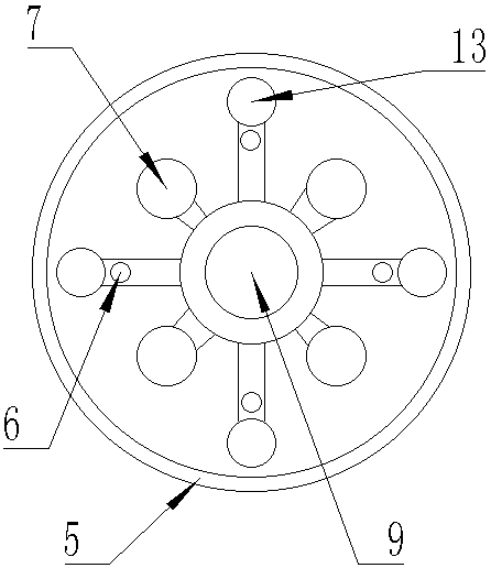
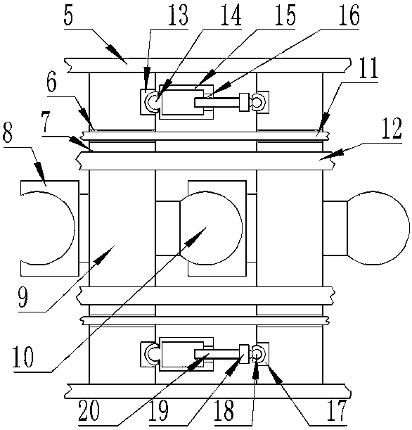

Image

  • Charging system control method used for charging new-energy automobile
  • Charging system control method used for charging new-energy automobile
  • Charging system control method used for charging new-energy automobile

Examples


Embodiment 1

[0048] On the basis of the above embodiments, the motor detection circuit can actually detect the running state of the motor and the rotation angle of the motor relative to the initial position, and then according to the structure of the charging line, the state of the charging line can be known, which is convenient for the central control unit to determine the charging state. The spatial state of the line, and then accurately control the movement of the charging line to realize the automatic operation of the charging line.

Embodiment 2

[0050] The charging system control method includes the following steps:

[0051] 1. When the car drives near the charging line 2, the position detection device detects the position information 001 of the car charging stand, and the position detection device sends the position information 001 to the central control unit;

[0052] 2. After the central control unit receives the location information 001, it calculates the distance L1 from the charging plug 3 to the car charging interface, and calculates the required shape of the charging line 2 according to this distance;

[0053] 3. The motor detection circuit converts the state of each driving motor into an electrical signal 002 and sends it to the central processing unit;

[0054] 4. After the central processing unit receives the electrical signal 002, it calculates the current state of the charging line 2, and calculates the number of turns and the direction of rotation of each motor according to the shape required by the char...


PUM


Abstract

The invention discloses a charging system control method used for charging a new-energy automobile. A charging system comprises a charging base connected with a flexible charging wire, and a chargingplug is connected to the top end of the charging wire. The charging wire is formed by multiple rigid charging knots connected in series, and every two charging knots can freely deflect around the axisof the charging wire. Drive mechanisms used for deflection of the charging knots are arranged between the charging knots. Each drive mechanism comprises a threaded rod used for providing power and athreaded hole, wherein the threaded rod and the threaded hole are connected in a matched mode. The charging system further comprises a control device in signal connection with the drive mechanisms. The control device comprises a central processing unit. The charging wire automatically and quickly moves, people uses the electric automobile conveniently, and the situation that people forgets to charge the automobile and thus the automobile cannot be used is avoided; and a pneumatic mode is adopted to achieve free motion of the charging wire, the motion structure of the charging wire is simple, cost is low, and economic benefits are high.

Description

technical field [0001] The invention relates to a charging device, in particular to a charging system control method for charging new energy vehicles. Background technique [0002] With the rapid development of society, the urban environment is gradually getting worse. In order to protect our living environment, new energy vehicles, especially pure electric vehicles, are gradually becoming popular. While the rapid development of the automobile industry promotes the development of the world economy and brings convenience to people, it also shows the other side of its double-edged sword, which brings serious problems to energy and the environment. "Energy, environment and safety have become the three major themes in the development of the world's automobile industry in the 21st century." Among them, energy and environmental issues, as the major challenges facing the world and the crux of the constraints that restrict the sustainable development of the automotive industry, hav...

Claims


Application Information

Patent Timeline
Patent Type & Authority Applications(China)
IPC IPC(8): B60L11/18H01R13/629H01R31/06
CPCB60L53/14B60L53/60H01R13/629H01R31/06H01R2201/26Y02T10/70Y02T10/7072Y02T90/12Y02T90/14
Inventor 朱森
Owner 朱森
Why Eureka
Eureka Blog
Learn More