Power converter

一种电能转换器、电能转换的技术,应用在输出功率的转换装置、电气元件、风能发电等方向,能够解决增加转换器成本、降低转换器整体效率等问题,达到改善准确度、增加数量、降低谐波失真水平的效果

Active Publication Date: 2018-03-27
OFFSHORE RENEWABLE ENERGY CATAPULT
View PDF6 Cites 2 Cited by
  • Summary
  • Abstract
  • Description
  • Claims
  • Application Information

AI Technical Summary

Problems solved by technology

However, further adding the number of modules increases the cost of the converter while reducing harmonic distortion
Additional switching components associated with additional ESD also introduce additional losses which reduce the overall efficiency of the converter

Method used


Image

  • Power converter
  • Power converter
  • Power converter

Examples


Embodiment Construction

[0059] In the drawings, like symbols indicate like parts.

[0060] Conventional Modular Multilevel Converter

[0061] Figure 1a A schematic diagram of a branch 101 of a conventional modular multilevel converter (MMC) is provided.

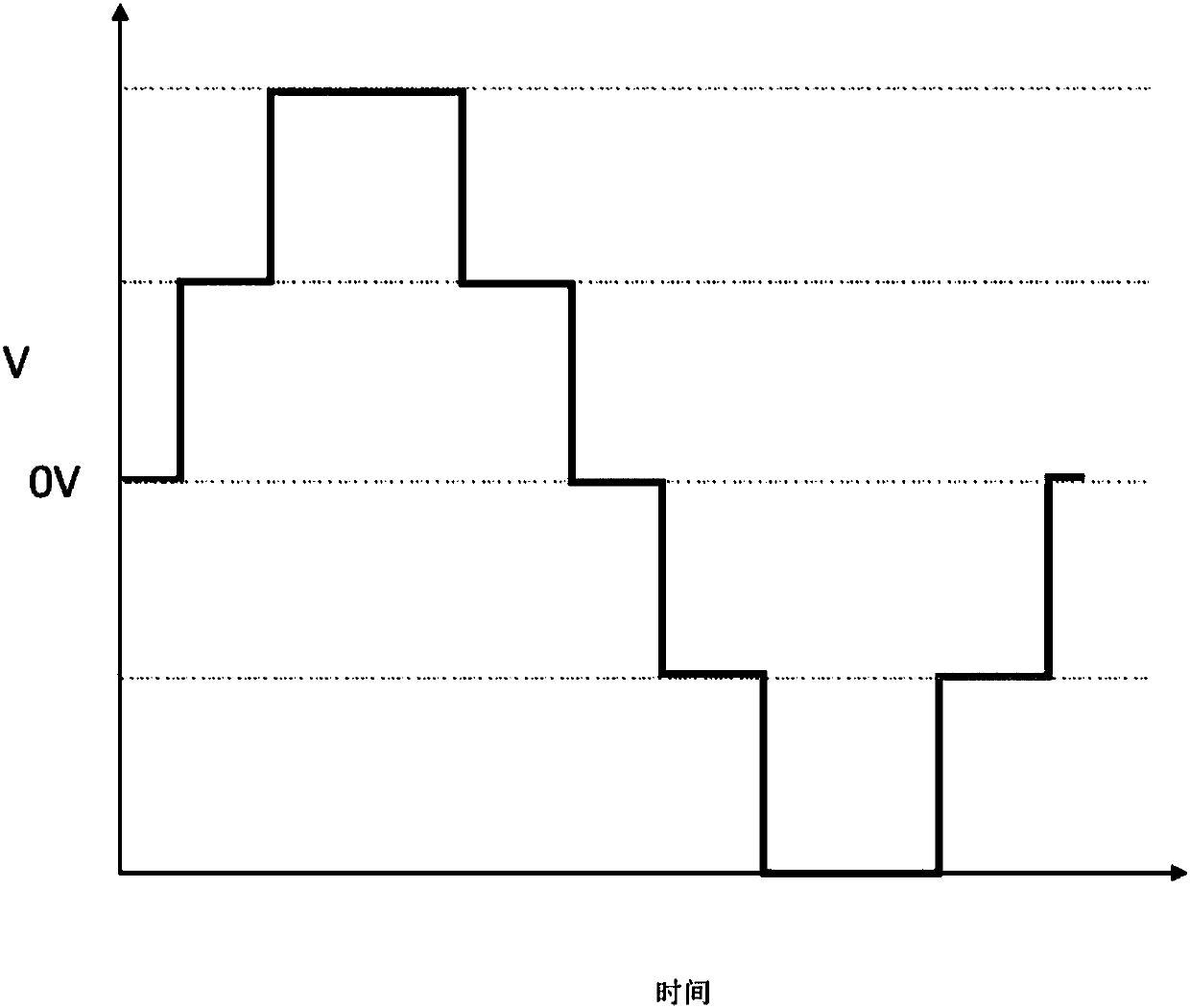
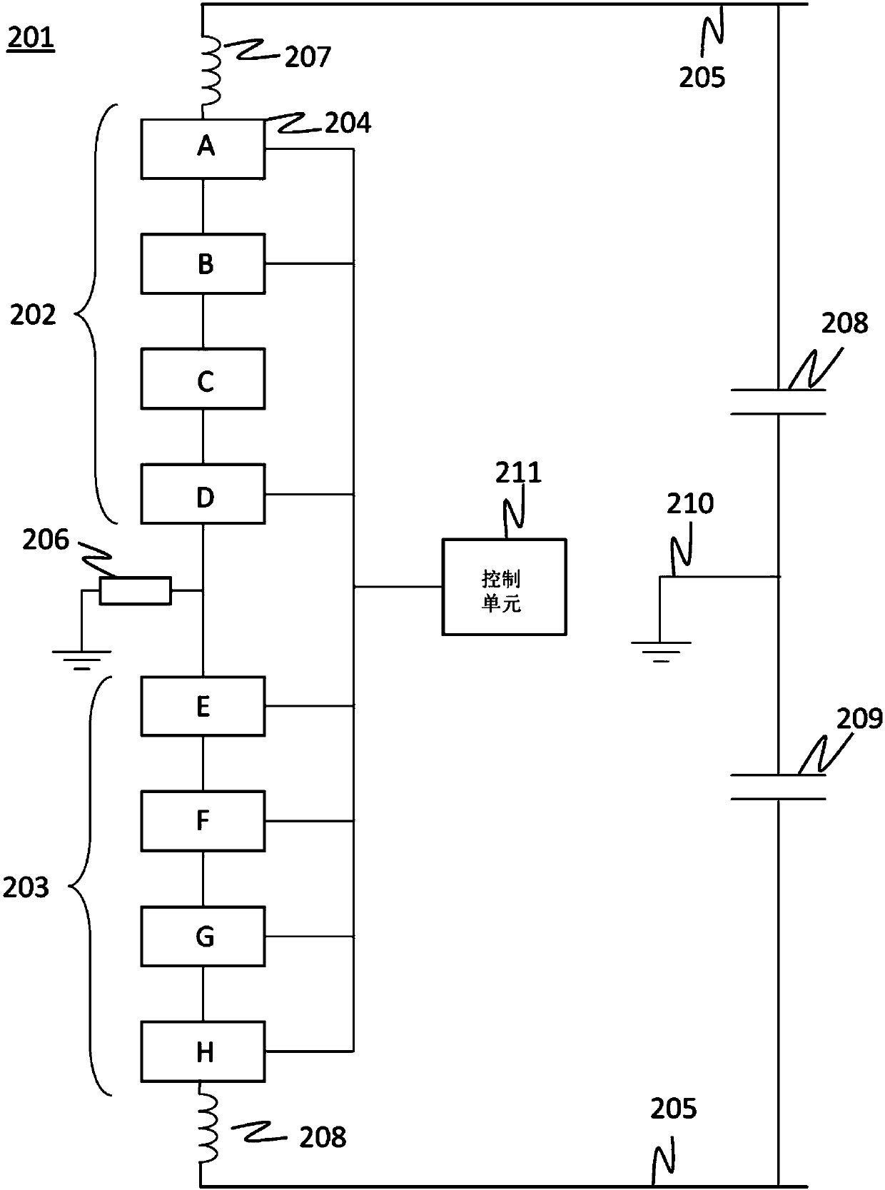
[0062] Branch 101 includes two identical subsections, subsection A1 and subsection A2 , each of which includes a plurality of modules 102 . The subsections, ie subsection A1 , subsection A2 are connected in series between the positive DC conductor 103 and the negative DC conductor 104 . The DC conductors 103, 104 are connected to the output of a high voltage direct current power supply typically providing a DC bus voltage VHVDO. In applications, a converter is used to convert electrical energy from a high voltage direct current (HVDC) power supply into a high voltage AC output suitable for power transmission. The converter includes Three such branches, each connected to the same high voltage direct current supply, (ie the same DC conductor), bu...


PUM


Abstract

A power conversion method comprising: charging a plurality of energy storage devices of a power converter from an input power source; and sequentially coupling and decoupling energy storage devices ofthe plurality of energy storage devices to an output. Charging the plurality of energy storage devices comprises maintaining at least two of the plurality of energy storage devices at substantially different potentials.

Description

technical field [0001] The present invention relates to techniques and devices for power converters and, in certain non-limiting examples, for converting high voltage DC input to AC output voltage (and vice versa) for power transmission. Background technique [0002] Typically, power distribution networks use high voltage AC infrastructure for power transmission. However, AC-related inductive and capacitive parasitic losses become increasingly problematic as distance increases. In some applications, such as electricity generated by offshore wind turbines that must be transported ashore by long submarine cables, it is more economical to use HVDC power transmission technology. Typically, a power converter is required to convert high voltage DC to AC (and vice versa) so that the generated electricity can be fed into the distribution network. [0003] When converting DC to AC, it is desirable to maximize electrical energy conversion efficiency (ie, minimize energy losses that ...

Claims


Application Information

Patent Timeline
Patent Type & Authority Applications(China)
IPC IPC(8): H02M7/501H02M7/483
CPCH02M7/501H02M7/4835Y02E10/76H02M7/483H02M7/49
Inventor C·H·吴P·麦基弗M·E·斯梅尔斯
Owner OFFSHORE RENEWABLE ENERGY CATAPULT
Why Eureka
Try Eureka