
Injection valve, exhaust-gas aftertreatment system

A technology of exhaust gas post-treatment and injection valve, which is applied in the direction of exhaust treatment, valve lift, control valve, etc., can solve the problems that the functional capacity of the injection valve can no longer be guaranteed, and achieve the effect of improving ice pressure resistance

Inactive Publication Date: 2018-03-27
ROBERT BOSCH GMBH
View PDF8 Cites 3 Cited by
  • Summary
  • Abstract
  • Description
  • Claims
  • Application Information

AI Technical Summary

Problems solved by technology

The disadvantage of this known solution is that due to the outwardly opening valve element only a hollow spray can be produced, and in the event of low temperatures leading to freezing of the reducing agent, the flawless functionality of the injection valve can no longer be guaranteed

Method used


Image

  • Injection valve, exhaust-gas aftertreatment system
  • Injection valve, exhaust-gas aftertreatment system

Examples


Embodiment Construction

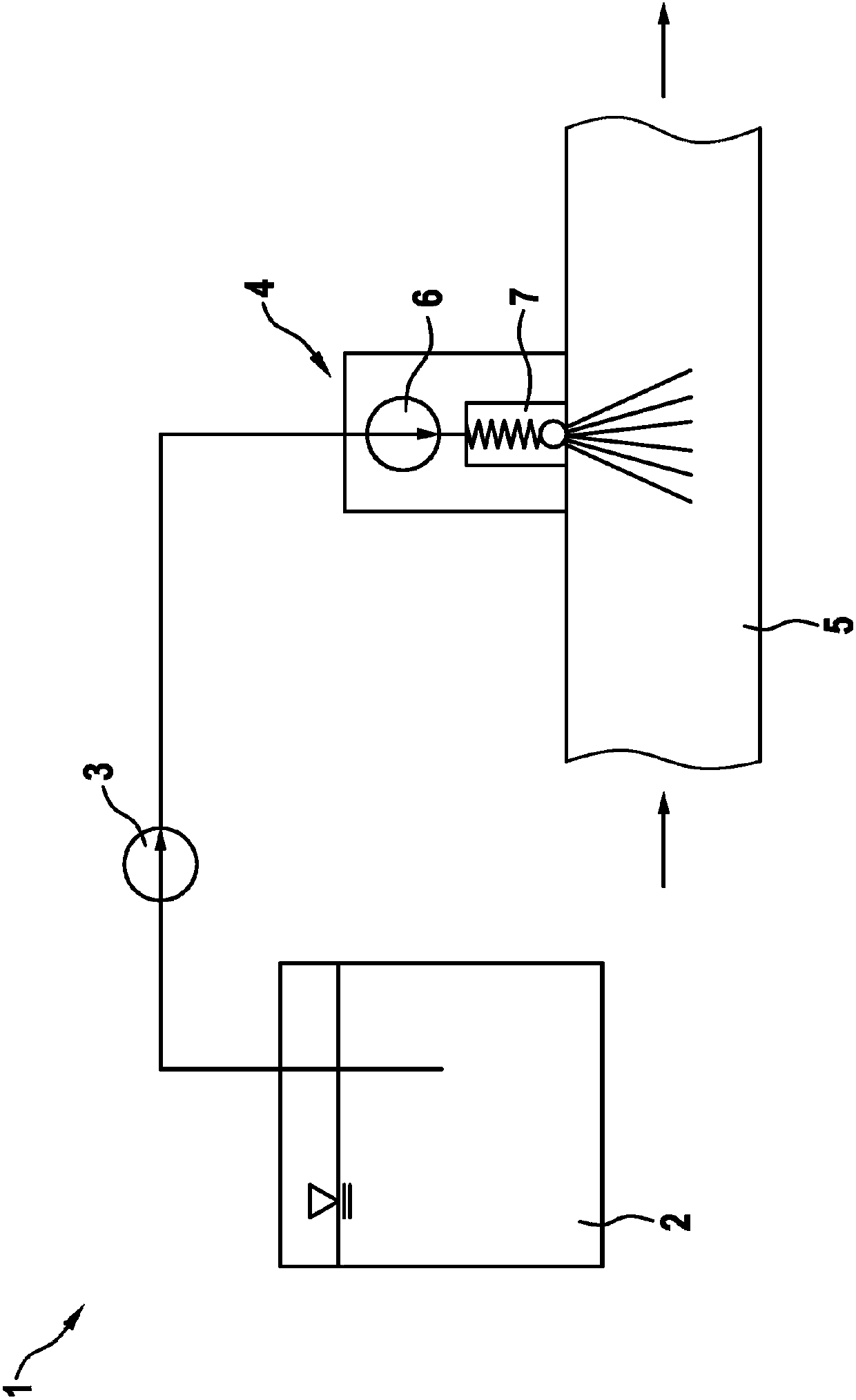
[0016] figure 1 An exhaust gas aftertreatment system 1 for a motor vehicle, not shown in detail here, is shown in schematic form. The exhaust gas aftertreatment system 1 has a tank 2 for storing and supplying a liquid reducing agent or exhaust gas aftertreatment agent, in particular an aqueous urea solution. Liquid reducing agent can be extracted from tank 2 by means of delivery pump 3 and delivered to injection valve 4 . The injection valve 4 is associated with an exhaust gas line 5 of an internal combustion engine of the motor vehicle (not shown in detail here) in order to inject reducing agent into the exhaust gas of the internal combustion engine. The injection valve 4 is designed here as a pump-nozzle unit, which includes an integrated delivery device 6 , in particular a pump, and a pressure-controlled valve 7 , shown here only in simplified form.

[0017] Due to the possibly long suction lines and the high temperatures in the exhaust pipe, it is advantageous to provide...


PUM


Abstract

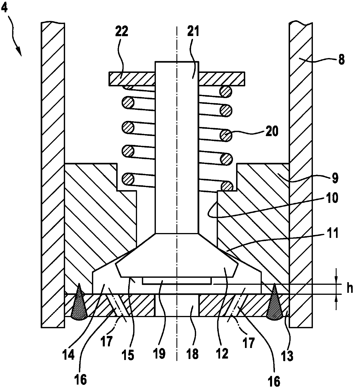
The invention relates to an injection valve (4), in particular of an exhaust-gas aftertreatment system (1), having an axially displaceable valve element (12), having a valve opening (10) which is assigned to a valve seat (11) of the valve element (12), having a piston (21) which is fixedly connected to the valve element (12) and which is led through the valve opening (10), and having a spring element (20) which forces the piston (21) with the valve element (12) against the valve seat (11), wherein the valve element (12) is displaceable in a spray chamber (14) which, opposite the valve element(12), has multiple spray openings (16, 18). It is provided that at least two first spray openings (16) have central axes (17) which intersect outside the injection valve, and / or that a centrally situated second spray opening (18) has a larger diameter than the other spray openings (16).

Description

technical field [0001] The invention relates to an injection valve, in particular an injection valve for an exhaust gas aftertreatment system of a motor vehicle, comprising: an axially displaceable valve element; a valve opening which is assigned a valve seat for the valve element; and a piston fixedly connected to the valve element, which passes through the valve opening; and a spring element, which presses the piston and the valve element towards the valve seat, wherein the valve element is displaceable in an injection chamber opposite the valve element The ground has multiple jet openings. [0002] The invention also relates to an exhaust gas aftertreatment system having such an injection valve. Background technique [0003] In motor vehicles with an internal combustion engine, owing to increasingly stringent exhaust gas regulations, the pollutant NOx must first be reduced in order to be able to comply with the regulations. A known method for reducing NOx pollutants is ...

Claims


Application Information

Patent Timeline
Patent Type & Authority Applications(China)
IPC IPC(8): F01N3/20
CPCF01N3/2066F01N2610/02F01N2610/1453Y02T10/12Y02A50/20F01N3/208F01N2610/1406F01N2610/1433F16K1/54F16K15/025
Inventor R·黑贝尔
Owner ROBERT BOSCH GMBH
Learn More