Radio frequency electro-thrombectomy device

一种射频、移除的技术,应用在射频电血栓清除装置领域,能够解决加热不均匀、损坏血管壁等问题,达到增强黏附、强化界面的效果

Active Publication Date: 2018-03-27
THE HONG KONG UNIV OF SCI & TECH
View PDF15 Cites 1 Cited by
  • Summary
  • Abstract
  • Description
  • Claims
  • Application Information

AI Technical Summary

Problems solved by technology

However, since heating is not uniform and decreases with distance from the lead, strengthening of the material at the perimeter would require high thermal energy at the lead, which could damage nearby vessel walls

Method used


Image

  • Radio frequency electro-thrombectomy device
  • Radio frequency electro-thrombectomy device
  • Radio frequency electro-thrombectomy device

Examples


Embodiment -

[0035] Example - Thrombus Removal

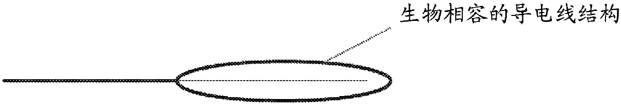
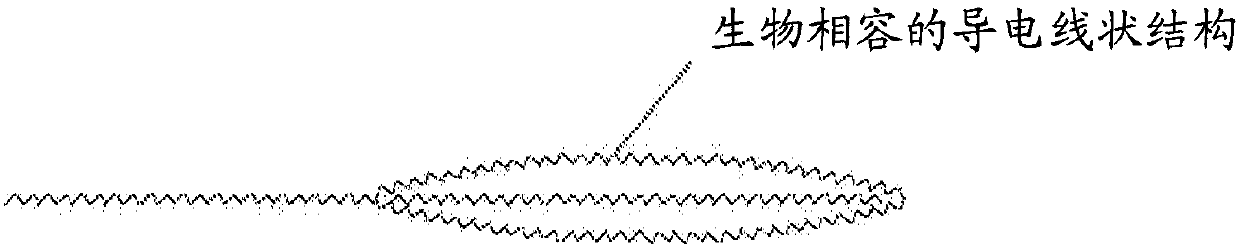
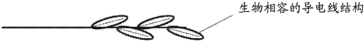
[0036] A device having a wire structure made of Nitinol and connected to a radio frequency (RF) system, such as one providing a 200 kHz current, is guided to the blood vessel occluded by the thrombus. The operating wires and structures of the device are deployed around the thrombus using standard surgical techniques. Then, connect the RF system to a power source. Radiofrequency current is applied to the blockage to induce cross-linking of substances in the thrombus. The thrombus is then removed along with the structure.

[0037] When used in an in vitro occlusion model, the operating wire and configuration of the radiofrequency electrothrombosis device of the present invention achieved 100% thrombus clearance and demonstrated to minimize the risk of remote embolism.


PUM


Abstract

A device is designed to remove blockages in a lumen such as a thrombus, blood clot, or embolus. The device comprises a manipulating wire and a structure that can conduct electrical current to a lumenblockage. The electrical current is preferably in radio frequency (RF). The RF electric current in the blockage can excite the contents such as proteins of the blockage, so that cross-linking densityand interfacial adsorption of the entire blockage is enhanced. The enhanced cross-linking density can result in increased fracture resistance of the blockage such that fracture of the blockage duringthe removal process is unlikely. The enhanced interfacial adsorption results in increased interfacial fracture resistance between the device and blockage so that the blockage can be securely capturedduring the removal process without using radially applied force.

Description

Background technique [0001] Diseases associated with blockages in different organs, including the brain and heart, such as ischemic stroke, are common fatal causes. An obstruction within a blood vessel, which may be a thrombus, clot or embolism, may reduce blood perfusion to downstream tissues. Vascular embolism refers to the formation or occurrence of a thrombus or blood clot within a blood vessel or cardiac cavity. A thrombus has two major components, aggregated platelets forming the platelet plug and a cross-linked fibrin mesh. Although blood clots are a normal response to injury and are designed to prevent bleeding, they can become harmful when they block the flow of blood in healthy blood vessels. Embolism is the movement of a thrombus or blood clot through the bloodstream until it cannot pass through the blood vessel and blocks circulation. If blood perfusion falls below a certain level, the body's cells cannot receive a sufficient amount of oxygen, and if the conditi...

Claims


Application Information

Patent Timeline
Patent Type & Authority Applications(China)
IPC IPC(8): A61B17/22
CPCA61B17/221A61B2017/22034A61B2018/0041A61B2018/00267A61B2018/00398A61B2018/00404A61B2018/144A61B2018/1475A61B18/1492A61B2018/00214
Inventor 袁铭辉郭正光林铨振庄智恒林嘉毅秦臻
Owner THE HONG KONG UNIV OF SCI & TECH
Why Eureka
Try Eureka